 It's been a while since I connected my ESP8266 board to a ZPUino soft processor running in a XuLA2 board. I thought I would update the firmware on the ESP8266 to the latest version and see if it still worked.
Since everyone is compiling new applications for the Espressif chip now, merely reprogramming the serial flash on the board should be easy, right? Just download a binary file and you're done! It turned out to be a bit more confusing.
Part of the confusion is that there are a lot of different programming tools being used: binary executables, Python scripts, whatever. Some tools require specifying four different binary files, one for each particular address range of the flash chip. But the downloadable archives don't usually have four files in them, and if they do, they don't have filenames matching the ones shown in the examples. I didn't want to brick my modules, even if they only cost $2.71/each.
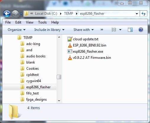
Finally, I settled on using the Espressif's official esp8266_flasher.exe program. I also downloaded the v0.9.2.2 AT Firmware.bin file.
After dumping the contents of both archives into a local directory, I had this:
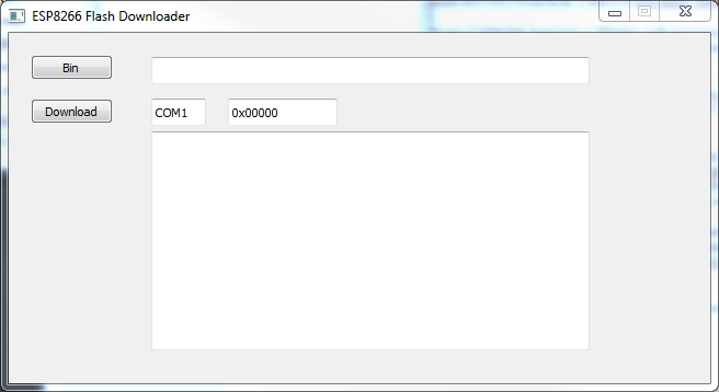
Double-clicking the esp8266_flasher.exe icon brought up the flashing tool:
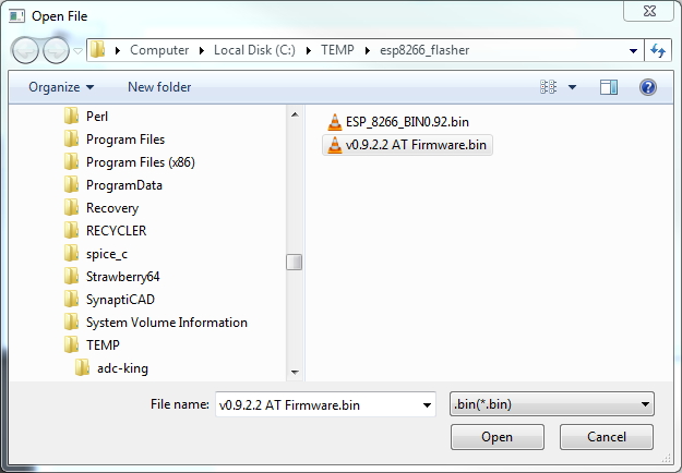
Clicking the Bin button opened a window where I selected the binary file to download into the serial flash of the board:
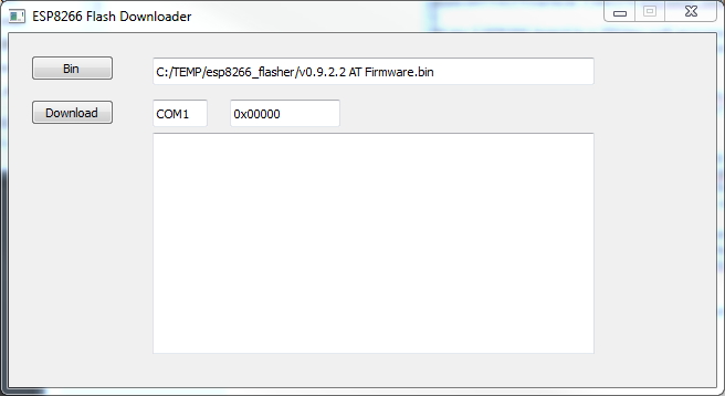
Selecting the v0.9.2.2 AT Firmware.bin file and clicking Open took me back to the main window with the firmware file displayed in the Bin field.
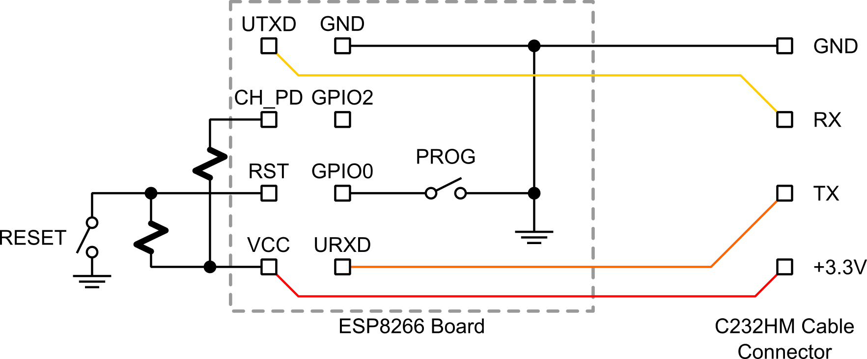
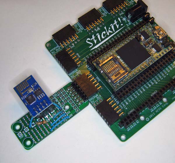
Next I needed to put the ESP8266 into its flash programming mode. This is done by resetting the ESP8266 board while holding its GPIO0 pin low. I could do this with a few wires and a breadboard but, since I might be doing this more than once, I decided to build a little programming board. It has a 4 × 2 socket for the ESP8266 board that is wired to a header where my C232HM USB-to-serial cable is attached. A couple of 2.2 KOhm pullup resistors for the chip-select and reset pins keep the ESP8266 enabled. PROG and RESET pushbuttons are provided to momentarily pull the GPIO0 and reset pins input to ground, respectively.
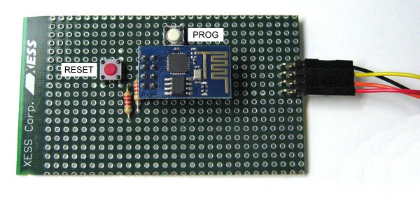
After inserting my ESP8266 board into the programming board and attaching the C232HM cable, I entered the flash programming mode by holding down the PROG button and then pressing and releasing the RESET button. In the flashing tool, I changed the serial port from COM1 to COM6 because that's where the CH232HM cable resides on my system. Clicking on the Download button started the reprogramming of the flash chip. The progress was displayed in the lower pane of the window and, after about a minute, the reprogramming was done.
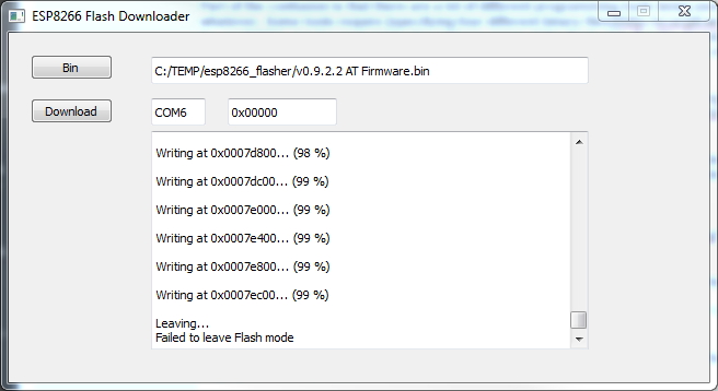
Note that the progress pane indicated "Failed to leave flash mode". That's probably because the flashing program doesn't have any way to bring the ESP8266 board out of programming mode. But it's not really a problem provided the contents of the flash chip were rewritten.
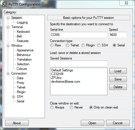
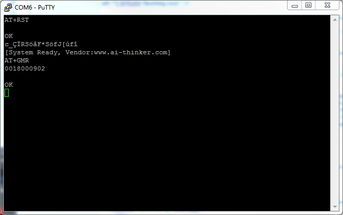
To verify the flash programming was successful, I needed to talk to the chip and query the firmware version. I closed the flash programming window and pressed the RESET button (without pressing the PROG button) to place the ESP8266 board in user mode. Then I brought up a PuTTY window and configured it as shown below.
Note that I set the speed to 9600 bps. The new firmware defaults to this communication rate rather than the 115 Kbps rate used in the factory-installed firmware.
After opening the PuTTY terminal window, I sent the ESP8266 the reset command (AT+RST) and then had it print the firmware version (AT+GMR). The version was shown to be 0018000902 rather than the 00160901 version that originally came loaded in the board. So the firmware update appeared to have worked.
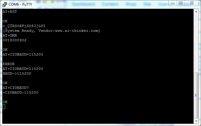
In order to push the transfer speed of the board back up to 115 Kbps (since the ZPUino can handle that speed, there's no need to cripple the interface), I used the AT+CIOBAUD=115200 command. Then I checked that the change took using the AT+CIOBAUD? command. (Observe that it required two attempts to change the baud rate, so don't be put off if that happens to you.) The baud rate is stored in nonvolatile memory so it will remain in effect from then on, even if the power is interrupted or a reset occurs.
With the new firmware in place and the baud rate back at 115Kbps, I took the ESP8266 module from the programming jig and put it back into my ZPUino development board. Now it was just a matter of running my existing program that downloads the contents of a web page over the wireless link, right?
Wrong! It turned out the update of the ESP8266 firmware is sufficiently different that the following minor changes were needed:
While making those changes, I also had to fix my code for timing-out if no characters were received from the ESP8266. The updated program can be found here.
So after all that, I finally had an updated Wifi module and a working example. I hope this procedure helps if you decide to update your own ESP8266.
Finally, if you're someone who would rather watch than read, then here's a video showing the entire process of updating the ESP8266 firmware:
Share on Twitter Share on Facebook Share on Reddit
Comments
Excellent article! Detailed, and to the point. The jig is a great idea, and I'll need to figure out how to build one for my 03 module... Oh, just one thing: You might want to put the video at the top of the article, just in case "someone who would rather watch than read" ;)
Link / ReplyHey, William. Thanks for the comment! I'll look at rearranging the video content.
Link / ReplyHi Dave,
Link / ReplyVery nice article, video and test board :)
Thank you.
What are the values of the pull up resistors ?
Thanks, Jas!
Link / ReplyThe pullup resistor values aren't critical. I used 2.2K for my programming jig. I think any value between 1K and 10K will work.
Hi do you have the url for the firmware please? id like to check for updates as 9.4 has been released
Link / ReplyYou can check for firmware here: https://drive.google.com/folderview?id=0B3dUKfqzZnlwRjFaNTUzZFptbzg&usp=drive_web
Link / ReplyGreat Article,
Link / ReplyCouple of questions
Is the ESP8266 you used a ESP-01 or ESP-03 or someother?
When do you release the PROG pushbutton? Do you hold it down the whole time the ESP8266 is being programmed?
I checked the link for updates to the firmware, it looks like its is now at Ver 9.5
Thanks
My board is the ESP-01 with the 8-pin connector. The ESP-03 has more I/O pins exposed and they're SMD-like, not pin headers.
Link / ReplyI press the PROG button and then press-and-release the RESET button. That puts the ESP8266 into programming mode. Once that's done, I release the PROG button.
Hello,
Link / ReplyI think i bricked 3 ESP8266 by performing the circuit. All worked fine until i pressed on the reset button i.e RESET to the ground, and thats all it goes into a garbage loop. Event completed disconnected and getting the same.
Tried disconnecting and connecting when the PROGRAM button (i.e GPIO0 connected to ground) and it starts without any loop (i can see the blue led not glowing) and unable to flash, the flashing tool gives 'Failed to connect'....any idea how to unbrick it......i am a looser tried the same reset button with all the three ESP i had :-(
Nazir, I don't have any real advice on this. Perhaps ask for help on some of the sites I listed here: http://www.xess.com/blog/esp8266-resources/
Link / ReplyIf worst comes to worst, you can always buy more. You can get another four ESP8266 modules for about $10 now.
I am trying to connect the esp 8266 to the arduino and trying to control a bulb using it. But there is a problem flashing the firmware.
Link / ReplyI made the connections according to the following link:
iot-playground.com/2-uncategorised/17-esp8266-wifi-module-and-5v-arduino-connection
I also connected the GPIO0 to gnd and rst,chpd,GPIO2 to 3.3v
But there is an error in flashing the firmware . "failed to connect".
Please help!!
I don't know what the problem is, Shabbir. I don't use an Arduino to program my ESP8266. Perhaps you should ask your question at the link where you found the flashing procedure you're using. Or try asking at one of the places I listed here: http://www.xess.com/blog/esp8266-resources/
Link / ReplyHi, I have a big problem with a module esp 8266, after accidentally typed the command AT + UPDATE not responding to AT commands.
Link / ReplyIn serial monitor appear an infinite number of alphanumeric characters.
I tried to reset, but the module does not respond.
you have any solution?
Thank you for those who answer me ..
Ok so I discover it wont work with Arduino using SoftSerial and I read that an ESP update is required.
Link / ReplyThe update files contain a file named cloud update.txt and it appears to have instructions for a cloud update.
Is this a FLASH update?
Its been loading data from the web for over half an hour right now.
The beginning of the file was corrupt, this is the instructions
1 ÔÆÉý¼¶¹¦ÄÜʹÓãº
ÏÈÓÃͨÓÃÉý¼¶³ÌÐò£¬ÉÕд0.92°æ±¾¹Ì¼þµ½ÄãµÄÄ£¿é£¡
2 È»ºó²ÎÕÕÏÂÃæÔÆÉý¼¶Ö¸ÁîÍê³É×îа汾Éý¼
Update steps
1.Make sure TE(terminal equipment) is in sta or sta+ap mode
ex. AT+CWMODE=3
OK
AT+RST
2.Make sure TE got ip address
ex. AT+CWJAP="ssid","12345678"
OK
AT+CIFSR
192.168.1.134
3.Let's update
ex. AT+CIUPDATE
+CIPUPDATE:1 found server
+CIPUPDATE:2 connect server
+CIPUPDATE:3 got edition
+CIPUPDATE:4 start start
OK
note. If there are mistakes in the updating, then break update and print ERROR.
I can't seem to send any commands to the ESP8266
Link / ReplyI reset it and I would get
@atal exception (0):
epc1=0x402191bf, epc2=0x00000000, epc3=0x00000000, excvaddr=0x00000000, depc=0x00000000
ets Jan 8 2013,rst cause:4, boot mode:(3,7)
wdt reset
load 0x40100000, len 212, room 16
tail 4
chksum 0x5e
load 0x3ffe8000, len 788, room 4
tail 0
chksum 0x1c
load 0x3ffe8314, len 72, room 8
tail 0
chksum 0x55
csum 0x55
jump to user1
I'm suppose to get a ready but it never appears. Does anyone know what's wrong? The main problem is the fact that I can't send commands. I've checked the wires and everything is in check. I just don't get a response from commands and the only response is from resetting on the RST pin.
Thank You
Link / ReplyI've tried <a href="http://smart-device.ir">flash</a> downoader but got this error:
connecting ....
Erasing flash...
Writing at 0x00000000... (0 %)
Invalid head of packet
How should I solve it?
Hi, I have the same problem (invalid header). Have you solved it?
Link / ReplyI have tried many different flashing tools and different firmware versions. I have grounded the GPIO0 already...
I almost got your program working on my Arduino UNO and ESP8266 firmware 0.9.5.0. The Arduino can send a maximum of 64 bytes to the ESP8266, but the string http_req (line 189) is longer than that. Can this be broken up as two requests? I get all the way into the while(true) loop at the very bottom (I put a print statement here to verify this) but I never see the ASCII graphics I expect. I tried removing the "HTTP/1.1" from http_req, but still no joy. Any help would be appreciated. Thanks.
Link / ReplyThe ESP8266 reacts to AT commands which are terminated by a newline. As long as you don't send a newline in the middle of a command, you should be OK. You could even send the command character-by-character and still be OK, I think.
Link / ReplyI was flashing and then this came out:
Link / ReplyWriting at 0x0000c000... (11 %)
Invalid head of packet
Do you have any idea about it? Thanks =D
I don't know what the problem is. Perhaps you should ask your question at one of the places I listed here: http://www.xess.com/blog/esp8266-resources/
Link / ReplyI had several invalid head of packet
Link / ReplyIt appears to be caused by my FT232RL, I have 10 of them, They all appear to work until you download , then the errors.
Only 2 out of the 10 will complete the download, 1 does not get any errors,[yet] ,, the other will get error sometimes may take 3 retries.
Have ordered some more from different China vendor to try...
Invalid head of packet - I was getting same error after going through 10 FT232RL adapters found only 2 that would download ok,,,,
Link / ReplyCurrently using FT232RL strapped +5 feeding sparkfun level board feeding ESP8266 ESP-201 with the 3.3 also feeding sparkfun board..
can telnet ok , cannot get +IPD to work , kind of lost now as what to do.
tried nodeMCU but was missing something, tried esp8266.ru FW looks promising, but lost output from cmds ???
You're a dead-set legend mate. I spent days trying to figure out what was wrong with my flashing rig, until I came across this. I added in a USB connector on to it as well so that it can be natively plugged in to a USB port, but otherwise, it's a great guide.
Link / ReplyReally appreciate your effort.
Hi Dave,
Link / ReplyAfter several attempts to recover the invalid state my ESP8266, your article saved me.
Very useful and well written. The strange thing is that my module worked properly when I bought it, and your procedure shows that it was not damaged ... the question then is why he went to the invalid state? Thanks again for your help and we will continue searching for the answer. (I speak Spanish, I used a translator to answer) Daniel
--- in spanish:
Luego de varios intentos por recuperar del estado invalido a mi ESP8266, tu articulo me salvó.
Muy útil y bien redactado. Lo extraño es que mi módulo funcionaba correctamente cuando lo compré, y tu procedimiento demuestra que no estaba dañado ... la pregunta entonces es ¿porqué pasó al estado invalido? Nuevamente gracias por tu ayuda y seguiremos buscando la respuesta. ( hablo español, usé un traductor para responder) Daniel
Hi Dave,
Link / ReplyExcellent write-up and brilliant take on the direct programmer. I wonder if is it worth to have a pull-up on GPIO0 so that its not left floating on the regular boot up mode ?
Many Thanks
Scott
Scott:
Link / ReplyMaybe, but my ESP8266-01 module was made to be used as-is and doesn't need an external pullup. So it's already on the -01 module or the chip has a built-in pullup or somethng.
I don't see how it would hurt to add one, however.
Good day
Link / ReplyI'm a beginner.
Unable to open the firmware file when I click on the Bin get an error-this is the log file:
Traceback (most recent call last):
File "esp8266_flasher.py", line 81, and ShowDialog
UnicodeEncodeError: 'ascii' codec can not encode character in '\ u010d' in position 59: ordinal not in range (128)
How do I fix this?
Sorry for bad english This is google translator.
Hello
Link / ReplyI'm a beginner with esp8266.
Following Instruction I pressed the button Bin chose v0.9.2.2 AT firmware folder and clicked open.
ESP Flash downloader does not react in the window does not open the file and log file gives the following error:
Traceback (most recent call last):
File "esp8266_flasher.py", line 81, and ShowDialog
UnicodeEncodeError: 'ascii' codec can not encode character in '\ u010d' in position 59: ordinal not in range (128)
How do I fix?
Sorry for bad english This is google translator.
Hey Dave,
Link / ReplyThanks a lot man! This post of yours, for flashing the firmware into the ESP8266 saved my day! I was struggling for whole day, searching across 100s of pages, to get a proper method to update my firmware on esp-12.
You gave a very clear instruction, and this flashing solved all of my problems! Being a newbie to esp8266, this was of great help!
Thanks again!
Hello, did you really use the C232HM (USB to MPSSE)? Maybe it was C232HD (USB to UART) instead?
Link / ReplyYes, I did use the C232HM cable. Works just fine!
Link / ReplyNew Comment