 I've gone through a bunch of resources about the ESP8266 Wifi module and verified that I have a couple of working units, so now it's time to start using them with a ZPUino softcore processor running on a XuLA2 board.
But before I could actually start writing programs, I needed to physically attach the ESP8266 module to a XuLA2 board. The module has an unfriendly 4x2 header that doesn't conveniently fit into a breadboard. And the arrangement of power, ground and I/O pins on the header doesn't match up with any of the connectors on the StickIt! board.
Then I remembered I designed some small StickIt! prototyping boards for last year's PyOhio class on programming FPGAs. I figured I could mount an ESP8622 module on one of those, insert it in a PMOD connector of a StickIt! board, and then insert a XuLA2 in the StickIt! board socket.
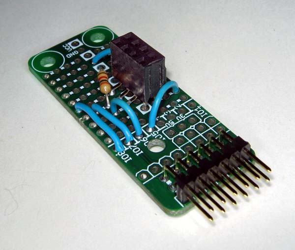
I didn't want to solder one of my ESP8266 modules to the prototyping board, so I decided to build a socket for it. I had some six-pin, right-angle PMOD sockets laying around, so I ripped out some pins, cut-and-sanded the socket housing, and bent the leads into a pattern to fit on the board as shown below.
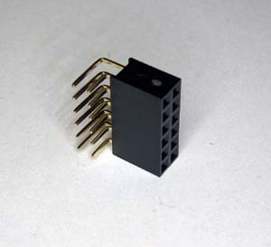
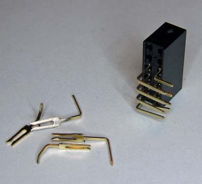
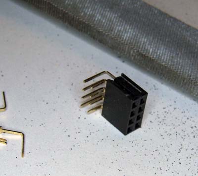
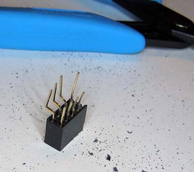
Then I mounted the modified socket and made connections from the serial TX and RX, reset, and select pins of the ESP8266 module to the PMOD interface of the prototyping board.
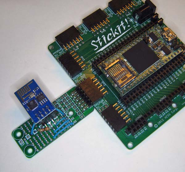
Finally, I inserted the ESP8266 module into the socket and attached the prototyping board to a StickIt! board with a XuLA2 FPGA board. Voilà, a nice, neat little package ready for programming!
Comments
Dave,
Link / ReplyI have spend almost a month trying to get a ESP8266 working.
Built a PIC24 board with dedicated header for the ESP at one
end and a USB at the other. Should have just started with a
soft core on an FPGA!!!
Thanks for posting your experience with delays.
Some possible info:
1. The "junk" on startup appears to be mostly ascii text at 76.8KB.
2. Firmware updates via Windows utility work ok.
3. If you have the newer firmware installed, you can update via the
Wifi itself.
4. Disabling the command echo "ATE0" seems to improve things
on my setup.
5. I use an I/O pin to toggle reset. RST is active low.
George
New Comment