 Over a year ago, I posted about how I reflashed an ESP-01 module with new firmware.
That post has been very popular and I got the idea in my head that I was some sort of expert on doing this.
But when I recently tried to do the same for an ESP-201 module, I found out I wasn't!
Over a year ago, I posted about how I reflashed an ESP-01 module with new firmware.
That post has been very popular and I got the idea in my head that I was some sort of expert on doing this.
But when I recently tried to do the same for an ESP-201 module, I found out I wasn't!
Backing up a bit, about a year ago I bought ten of the -201 modules on Aliexpress for $33. (Now you can get the same thing for $26.) I was going to do something with them; I've quite forgotten what that was.
But I've become interested in integrating the ESP8266 chip in another project so I thought I'd pull these out and get reacquainted. The ESP8266 has been integrated into the Arduino environment since I last looked, and that would be an easy way for me to reprogram the chip.
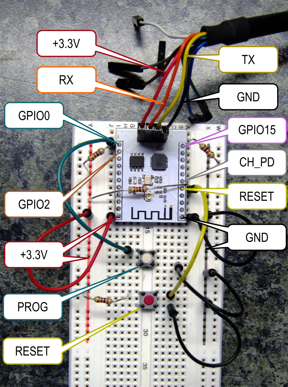
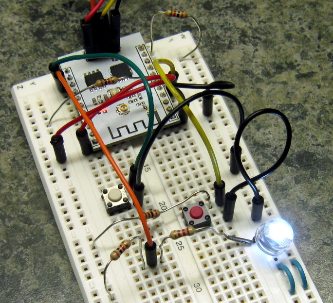
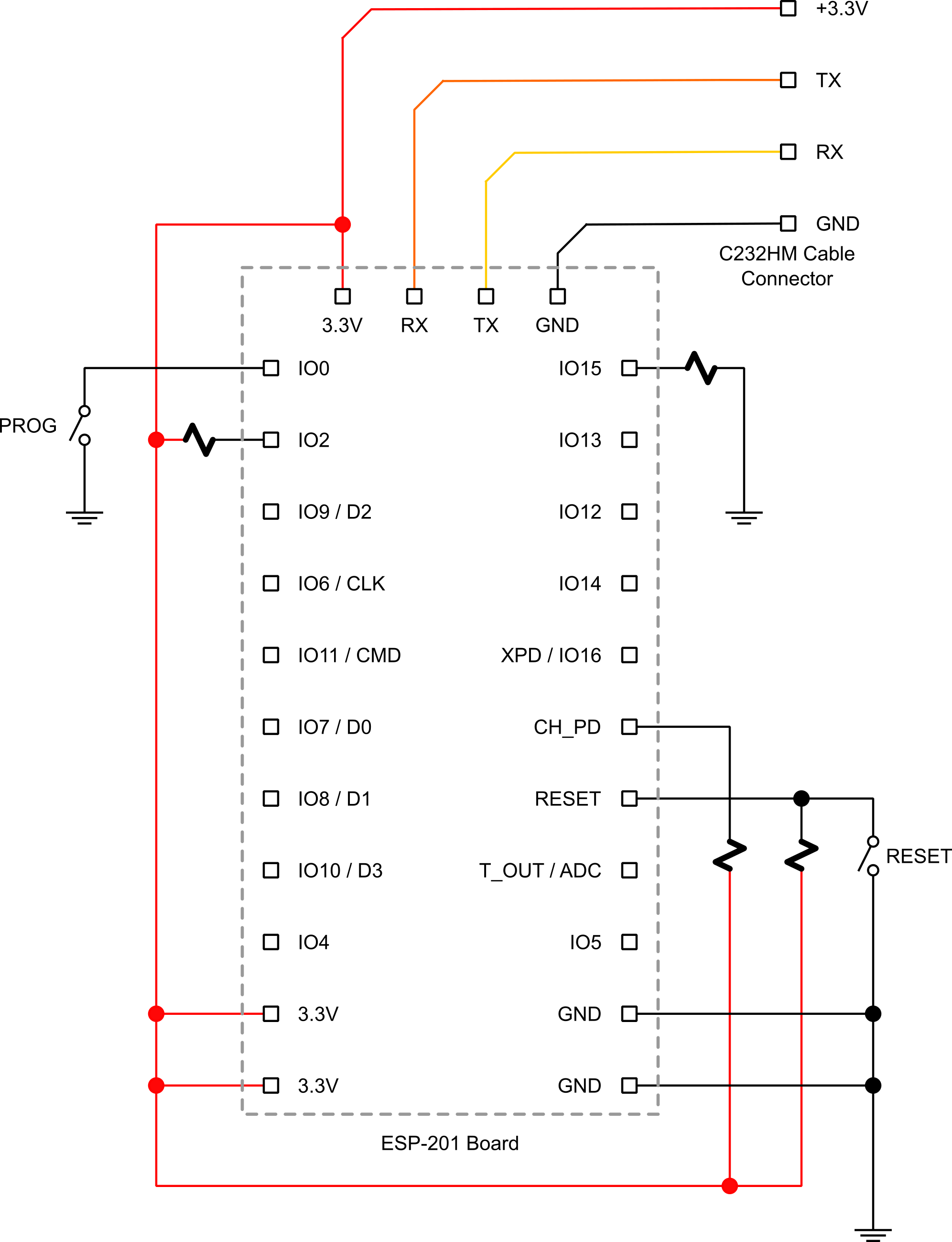
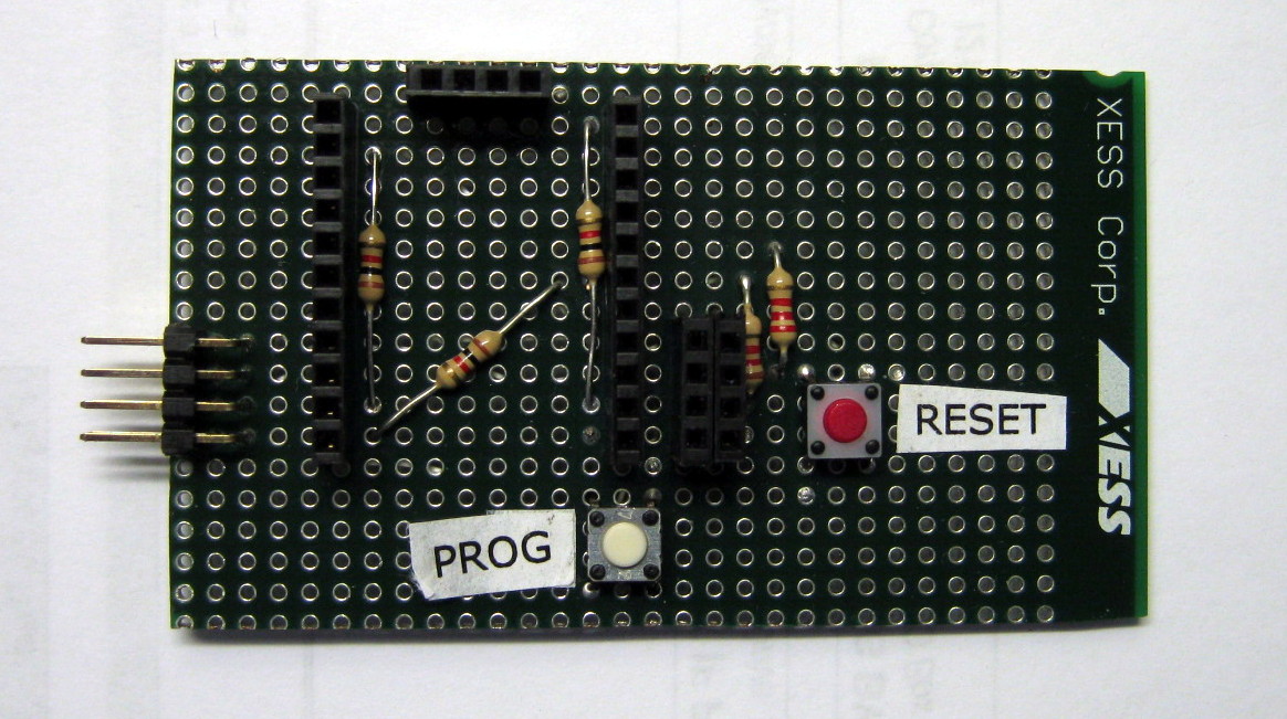
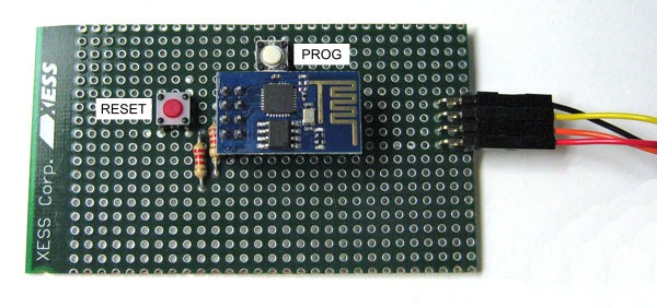
The first thing I did was connect some resistors, buttons, jumpers and my C232HM cable to the pins of the ESP-201 module in a manner similar to what I did previously for the ESP-01 module:
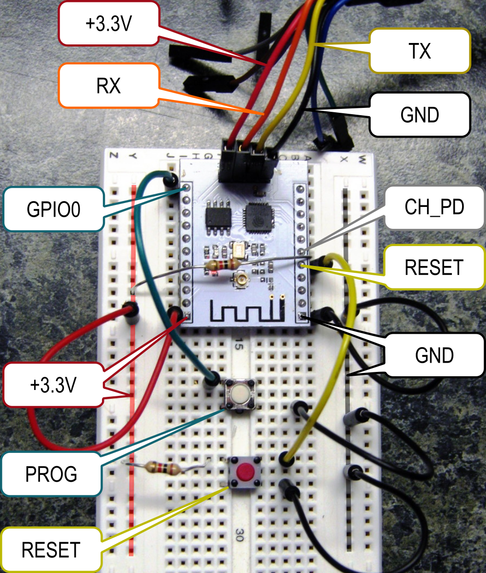
(Note that in the photo above, the RX and TX labels apply to the serial
receiver and transmitter pins of the -201 module.
The attached C232HM cable leads have the opposite functions.)
I put the ESP8266-201 module into flash reprogramming mode using the same procedure as for the ESP-01 module:
PROG button,RESET button, PROG button.Next, I downloaded and installed the latest Ardunio IDE.
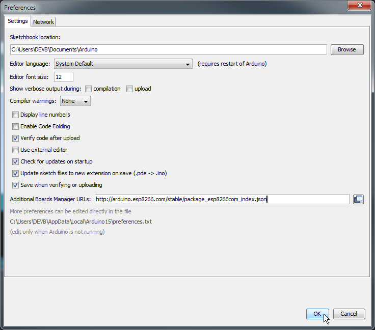
It doesn't support the ESP8266 out of the box, so I opened the File => Preferences
dialog box and entered http://arduino.esp8266.com/stable/package_esp8266com_index.json
into the Additional Boards Manager URLs field.
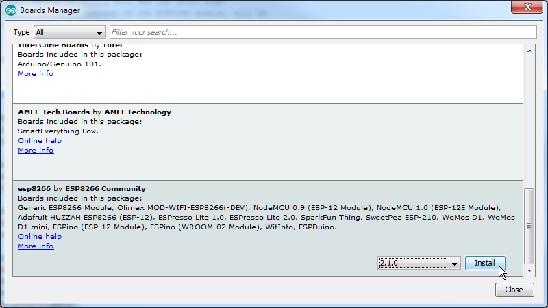
Then I clicked on Tools => Board: => Boards Manager....
At the bottom of the Boards Manager window that appeared, I found the esp8266 entry and clicked on it.
Then I clicked on the Install button which downloaded and installed the
appropriate compiler & linker (plus code samples).
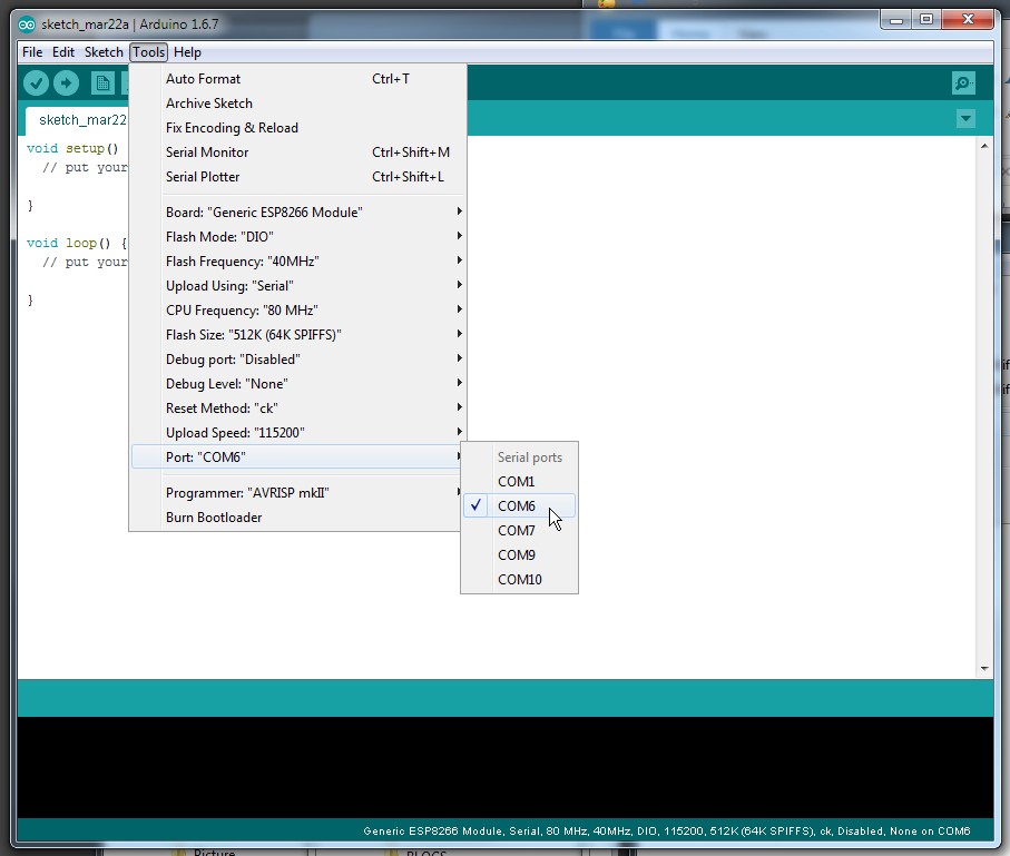
In order to work with the ESP-201 module, I selected the Generic ESP8266 Module entry from the list of boards:
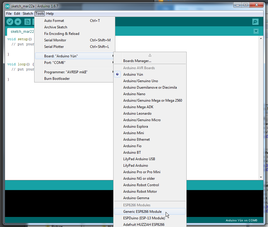
Selecting this entry reconfigures the Tools menu with new options having default values.
The only thing I changed was the port for my C232HM cable:
Now that I had my environment set up, I needed something to compile and run to test my board.
I selected the WiFiWebServer: an application that turns an LED on and off
when a particular web page served by the ESP8266 is accessed.
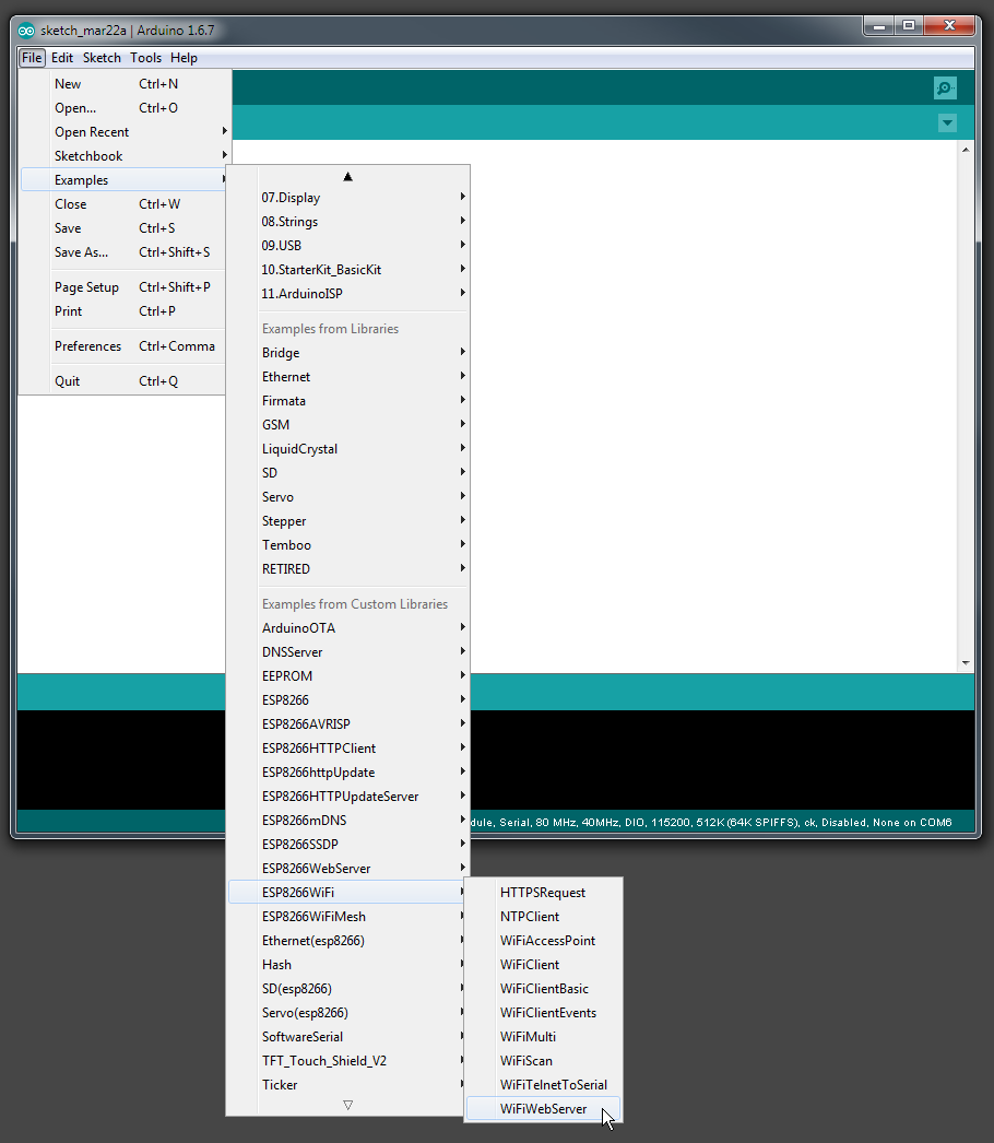
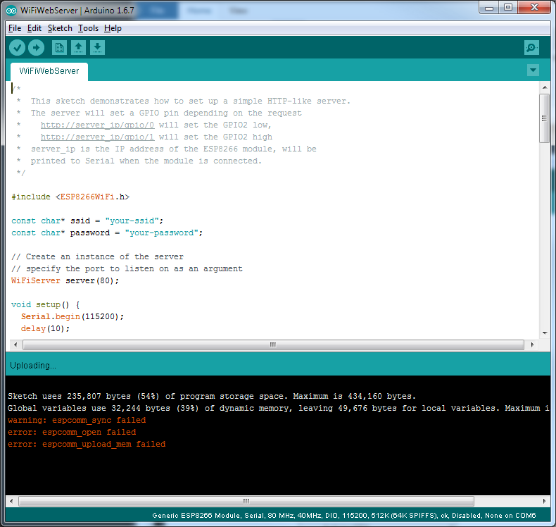
Once the project loaded, I just selected Sketch => Upload to see if it would
compile and get programmed into my -201 module.
Naturally, it failed:
OK, that's not surprising: the -201 module may need a different set up than the -01 module. After searching for a while, I found this handy ESP-201 cheat sheet. It indicated that for the ESP-201 to enter the flash mode, the GPIO2 and GPIO15 pins had to be attached to +3.3V and ground, respectively. I added a few jumpers to do that, repeated the steps for putting the ESP-201 into programming mode, and tried another upload...
Failure.
From there, I tried various combinations of options under the Tools menu:
different upload speeds, different COM ports, different board frequencies,
different flash settings...
Failure. Failure. Failure. Failure.
My next thought was that maybe the AT firmware in my modules was too old to work with the Arduino uploader. I installed the ESP Flash Download Tool by Espressif and then downloaded a fresher version of the AT firmware that would fit into the 4 Mb flash on my -201 modules. But when I tried the tool, it wouldn't link to my module, either.
So I went looking for another program to update the firmware. I decided to try esptool.py since it is mentioned frequently. There, halfway down its README page, I found this:
The following ESP8266 pins must be pulled high/low for either normal or serial
bootloader operation. Most development boards or modules make these connections
already, internally:

| GPIO | Must Be Pulled |
--------------------------
| 15    | Low/GND (directly, or with a resistor) |
| 2     | High/VCC (always use a resistor) |

If these pins are set differently to shown, nothing on the ESP8266 will work as expected.
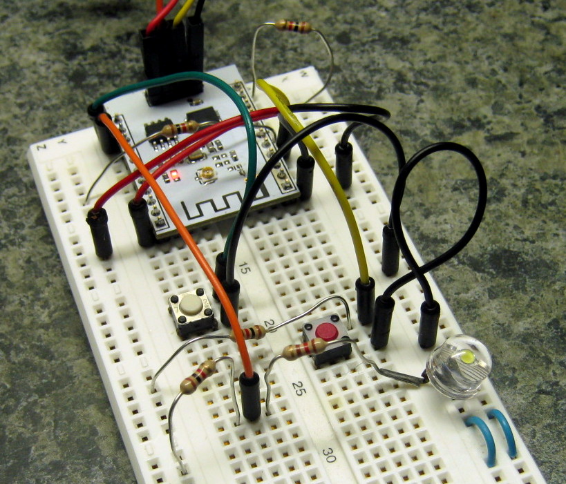
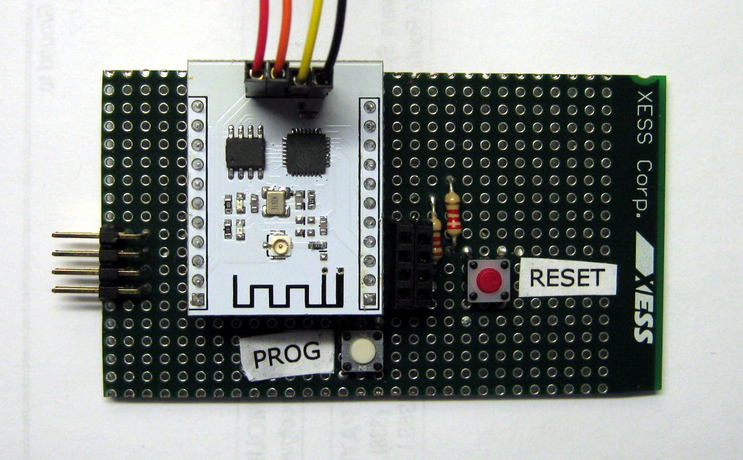
There was my problem: I had tied GPIO2 to +3.3 directly rather than through a resistor. So I replaced the jumpers on the GPIO2 and GPIO15 pins with 1K resistors as shown below:
Then I tried the Arduino uploader again:
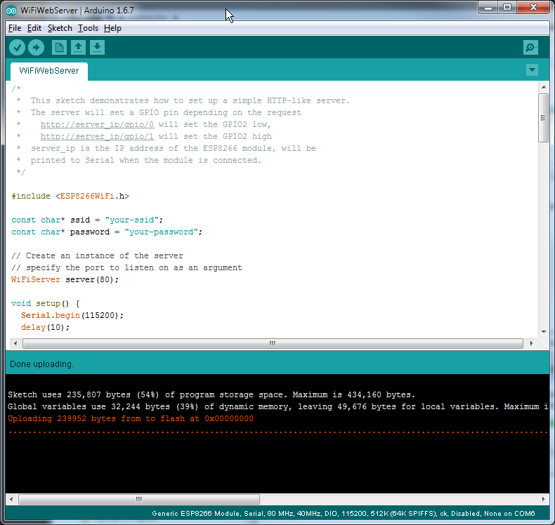
Success!
OK, now I could upload to my ESP-201 module.
I edited the web server code to enter the SSID and password for my local WiFi network
and then recompiled and uploaded it to my board.
Then I clicked on Tools => Serial Monitor to bring up a window that would show
status messages output by the web server.
Pressing the RESET button (without pressing the PROG button) initiated
the web server and it put out the following information:

These indicated that the web server had started and connected to the local WiFi with the displayed IP address.
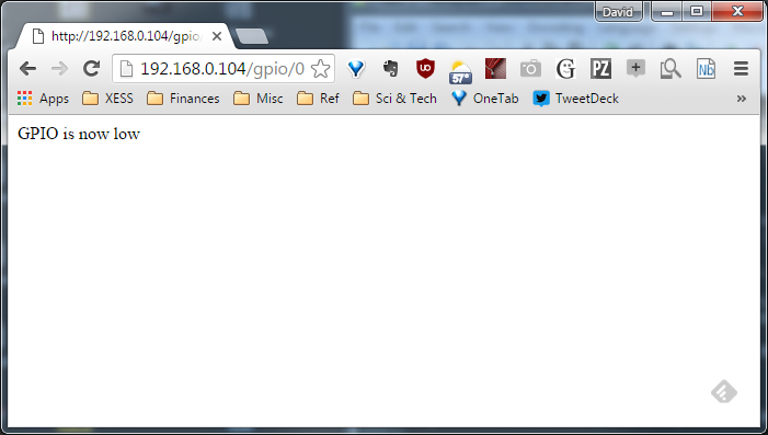
The web server outputs a high or low level on the GPIO2 pin depending upon the
web page that's accessed.
To observe the output level, I connected an LED plus a current-limiting resistor
from the GPIO2 pin to ground.
Then I just opened a web browser and went to the pages shown below to turn the LED on and off.

So after a lot of effort and a few dead ends, I had my ESP-201 boards working with the Arduino IDE. In order to make it easier in the future to program the modules, I used the schematic shown below and added the necessary sockets and components to a programming board I previously built for the ESP-01:
I hope this post will help you get started with using your own ESP-201 modules. Even if you use a different programming environment than the Arduino IDE, the steps for building the programming hardware may still save you from the mistakes I made.
Finally, if you're someone who would rather watch than read, then here's a video showing the entire process of building the hardware for the ESP-201 and reprogramming it with the Arduino IDE:
Share on Twitter Share on Facebook Share on Reddit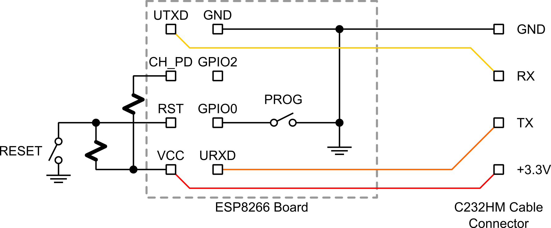
Comments
New Comment