 In previous posts, I've
introduced the ZPUino softcore processor
and shown how to build the base instance for an FPGA.
But the real advantage of the ZPUino is being able to extend it by attaching new peripherals
to the core processor in the VHDL description.
The best way to learn something is by doing it, so in this post I'll show how to integrate a
simple RGB LED driver peripheral into the ZPUino.
The ZPUino architecture incorporates 16 slots that can be populated with peripherals. A particular slot is activated when the ZPUino core processor accesses an I/O address within the range of addresses assigned to that slot. Then the peripheral in that slot can pass data back-and-forth with the processor through a Wishbone interface that consists of parallel address and data buses along with control signals and a handshake synchronization protocol.
The Wishbone interfaces to peripherals are instantiated in the top-level module of the ZPUino VHDL code. Within the module are empty slots like this:
--
-- IO SLOT 9
--

slot9: zpuino_empty_device
port map (
  wb_clk_i  => wb_clk_i,          -- Clock to peripheral.
  wb_rst_i  => wb_rst_i,          -- Reset to peripheral.
  wb_dat_o  => slot_read(9),      -- Data from peripheral.
  wb_dat_i  => slot_write(9),     -- Data to peripheral.
  wb_adr_i  => slot_address(9),   -- Address to peripheral.
  wb_we_i   => slot_we(9),        -- Write-enable to peripheral.
  wb_cyc_i  => slot_cyc(9),       -- Cycle handshake to peripheral.
  wb_stb_i  => slot_stb(9),       -- Chip-select to peripheral.
  wb_ack_o  => slot_ack(9),       -- handshake acknowledge from peripheral.
  wb_inta_o => slot_interrupt(9), -- Interrupt from peripheral.
  id        => slot_ids(9)        -- Peripheral ID (not part of Wishbone).
);
All the signals are part of the Wishbone interface except for id which outputs a peripheral-specific code
that the ZPUino processor can use to associate a peripheral performing a specific function
(e.g., a UART) with software drivers for that function.
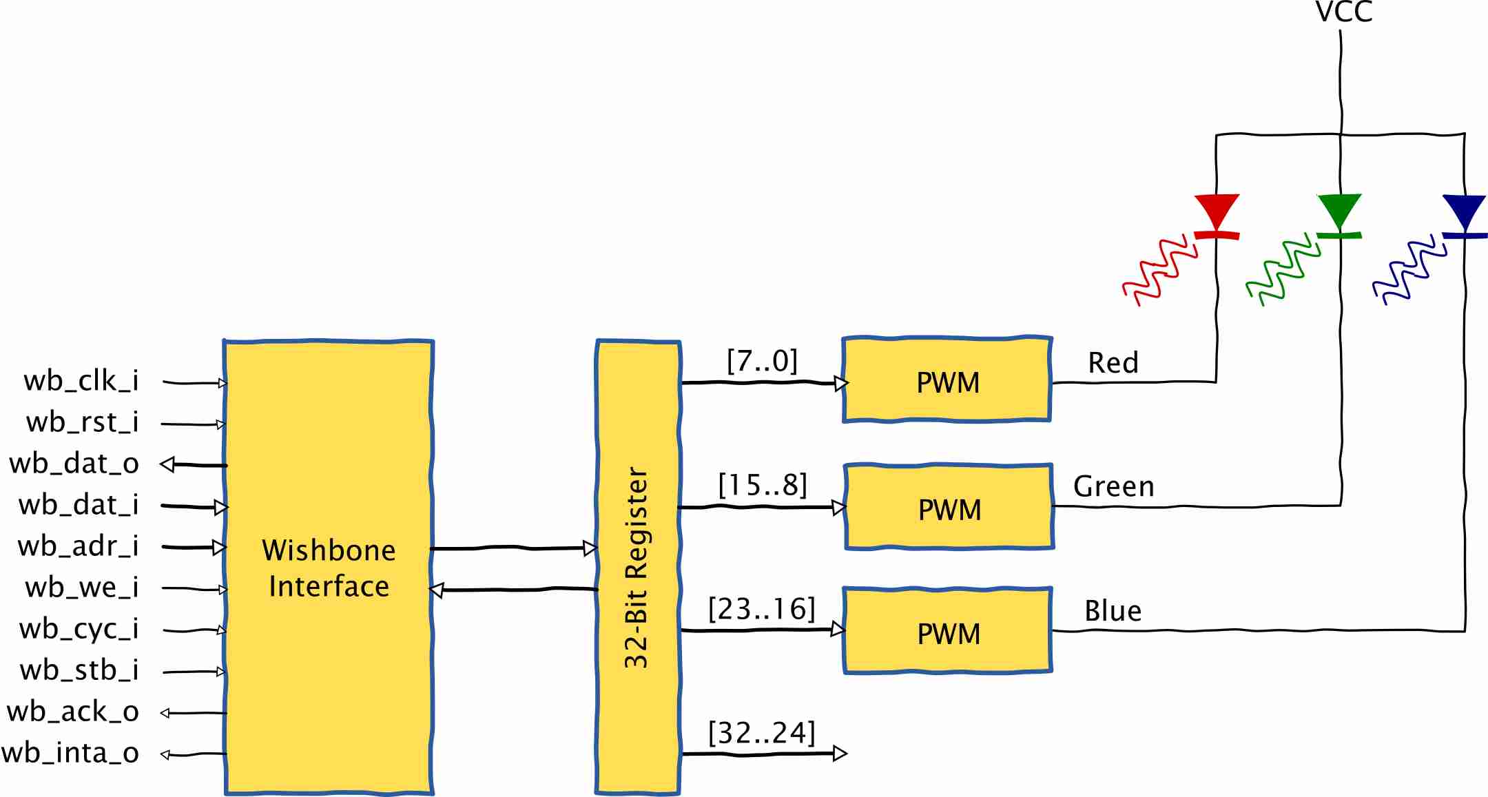
I constructed the RGB peripheral according to the following block diagram:

The Wishbone interface allows the processor to read or write a single 32-bit register at address 0. Each of the lower three bytes of this register controls the duty-cycle of a pulse-width modulator (PWM). Varying the duty cycles of the PWMs will change the intensities of the red, green and blue components which changes the overall color of the RGB LED. For the excruciating operational details, check out the VHDL for the PWM and the RGB peripheral.
Next, I instantiated the RGB peripheral in the top-level ZPUino module as follows:
--
-- IO SLOT 9
--

slot9: WbRgbLed
port map (
  wb_clk_i      => wb_clk_i,
  wb_rst_i      => wb_rst_i,
  wb_dat_o      => slot_read(9),
  wb_dat_i      => slot_write(9),
  wb_adr_i      => slot_address(9),
  wb_we_i       => slot_we(9),
  wb_cyc_i      => slot_cyc(9),
  wb_stb_i      => slot_stb(9),
  wb_ack_o      => slot_ack(9),
  wb_inta_o     => slot_interrupt(9),
  id            => slot_ids(9),
  redLed_o      => led_r, -- Output for driving red led.
  grnLed_o      => led_g, -- Output for driving green led.
  bluLed_o      => led_b  -- Output for driving blue led.
);
The led_r, led_g, and led_b output signals have to be attached to pins of the ZPUino
in order to connect to the physical RGB LED. I could have made these pin assignments
statically, but the ZPUino provides a much more flexible solution with its
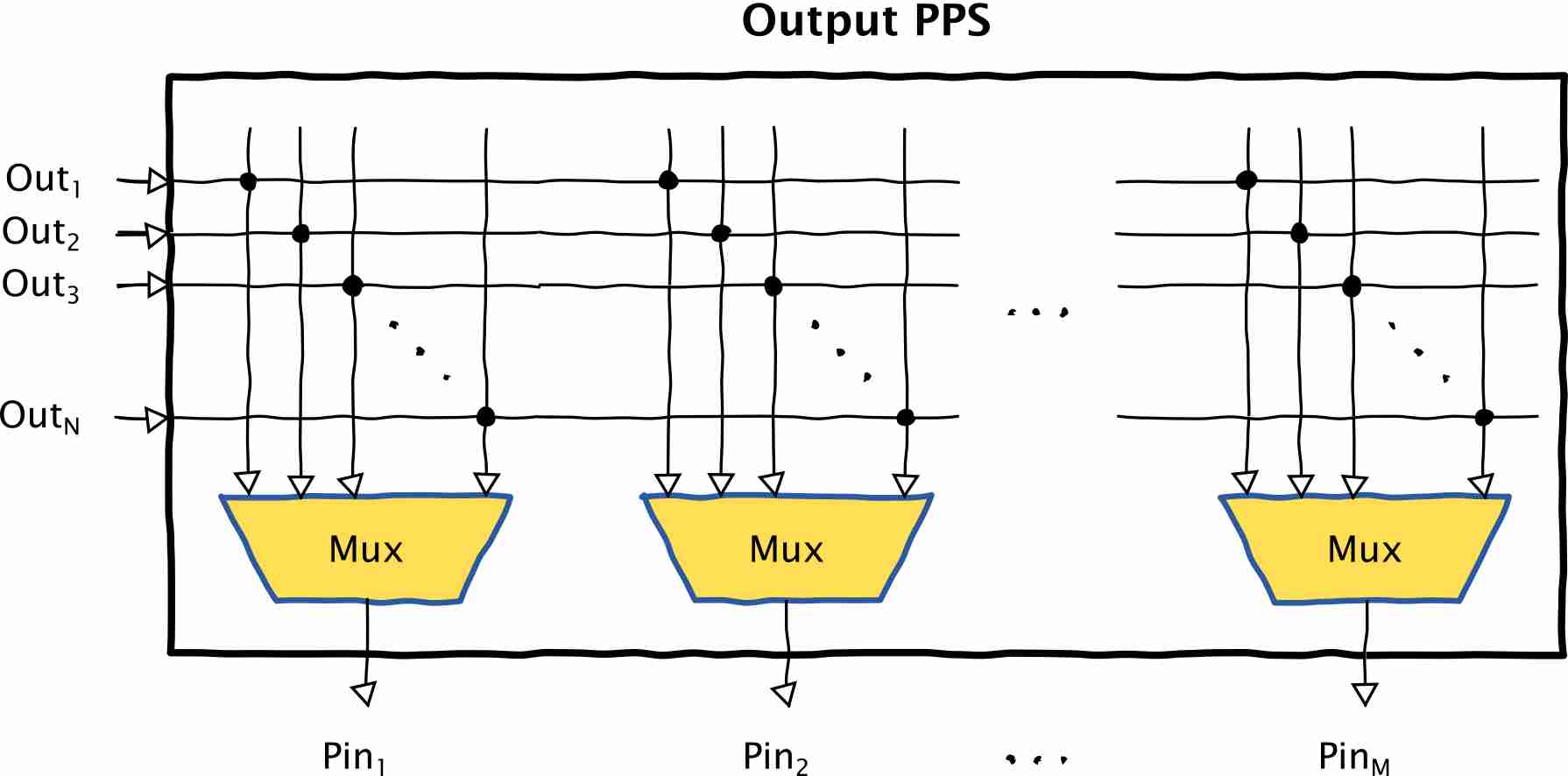
Peripheral Pin Select (PPS) mechanism. The PPS is basically a collection of
multiplexers that allow any one of N outputs to be attached to any one of M
pins under software control. (There is an equivalent PPS block for redirecting the inputs.)
So with the PPS, I can assign the ZPUino pins that output the RGB PWM signals at run-time.

Within the top-level ZPUino VHDL module, I attached the RGB peripheral outputs to the output PPS as follows:
process(gpio_spp_read, spi_pf_mosi, spi_pf_sck,
        sigmadelta_spp_data,timers_pwm,
        spi2_mosi, spi2_sck, led_r, led_g, led_b )
begin

  gpio_spp_data <= (others => DontCareValue);

  -- PPS Outputs
  gpio_spp_data(0)  <= sigmadelta_spp_data(0);   -- PPS0 : SIGMADELTA DATA
  ppsout_info_slot(0) <= 5; -- Slot 5
  ppsout_info_pin(0) <= 0;  -- PPS OUT pin 0 (Channel 0)
  .
  .
  .
  gpio_spp_data(6)  <= uart2_tx;   -- PPS6 : UART2 TX
  ppsout_info_slot(6) <= 8; -- Slot 8
  ppsout_info_pin(6) <= 0;  -- PPS OUT pin 0 (Channel 1)

  -- Attach the RGB LED driver outputs to the PPS outputs.
  gpio_spp_data(7)  <= led_r;   -- PPS7 : Red LED driver
  gpio_spp_data(8)  <= led_g;   -- PPS8 : Green LED driver
  gpio_spp_data(9)  <= led_b;   -- PPS9 : Blue LED driver

  -- PPS inputs
  spi2_miso         <= gpio_spp_read(0);         -- PPS0 : USPI MISO
  ppsin_info_slot(0) <= 6;                    -- USPI is in slot 6
  ppsin_info_pin(0) <= 0;                     -- PPS pin of USPI is 0

  uart2_rx          <= gpio_spp_read(1);         -- PPS1 : UART2 RX
  ppsin_info_slot(1) <= 8;                    -- USPI is in slot 6
  ppsin_info_pin(1) <= 0;                     -- PPS pin of USPI is 0

end process;
In order to make room in the PPS for the new outputs, I bumped-up the PPSCOUNT_OUT constant in the
zpuino_config.vhd
file:
-- Set this to the max. number of output pps on the system
constant PPSCOUNT_OUT: integer := 10; -- Increased to handle RGB LED drivers.
After making these changes, I rebuilt the ZPUino FPGA bitstream with the newly-added RGB peripheral. Now it's just a matter of writing the software for accessing the new peripheral. I'll demonstrate this by writing an example program that ramps-up and then fades an RGB LED over a sequence of colors.
The program starts (as most do) with a set of definitions. This is where I tell the program about the decisions I made in the VHDL code: the location of the RGB peripheral (slot 9), the address offset of the color register (0), and the position of the red, green and blue outputs going into the PPS block (7, 8, and 9). I also specify the ZPUino pins that the RGB LED will be connected to (5, 4 and 3).
// Slot the RGB peripheral is assigned to.
#define RGB_SLOT 9
// Address of the color register in the RGB peripheral.
#define COLOR_REG 0
// Position of the red, green and blue PWM outputs
// within the PPS output block.
#define RED_PPS_POS 7
#define GRN_PPS_POS 8
#define BLU_PPS_POS 9
// ZPUino pins for driving an RGB LED.
#define RED_PIN 5
#define GRN_PIN 4
#define BLU_PIN 3
Next, I use these definitions in the setup() routine.
The ZPUino pins driving the RGB LED are enabled as outputs,
and these outputs are driven by the multiplexers from the PPS.
Then each multiplexer is programmed to output one of the PWM signals
from the RGB peripheral.
void setup() {
  // Enable the outputs to the RGB LED.
  pinMode(RED_PIN, OUTPUT);
  pinMode(GRN_PIN, OUTPUT);
  pinMode(BLU_PIN, OUTPUT);
  // Enable the peripheral pin multiplexer for the outputs.
  pinModePPS(RED_PIN, HIGH);
  pinModePPS(GRN_PIN, HIGH);
  pinModePPS(BLU_PIN, HIGH);
  // Map the PWM outputs to the RGB output pins.
  outputPinForFunction(RED_PIN, RED_PPS_POS);
  outputPinForFunction(GRN_PIN, GRN_PPS_POS);
  outputPinForFunction(BLU_PIN, BLU_PPS_POS);
}
Then there's the little set_rgb_color() subroutine that accepts a 24-bit color value
and writes it to the color register within the RGB peripheral.
The IO_SLOT(RGB_SLOT) macro-call generates the base address for the RGB peripheral.
Then the REGISTER(...) macro-call adds the offset of the color register
to the base address to generate the final address where the new color value is written.
void set_rgb_color(unsigned int color)
{
  REGISTER(IO_SLOT(RGB_SLOT), COLOR_REG) = color;
}
The meat of the example program is contained in the brighten_then_fade() subroutine that ramps the RGB LED
up to its maximum color intensity and then down to zero.
It accepts a color_increment argument that contains either a 0 or a 1
in each of its eight-bit fields.
For example, the value 0x000101 would change both the red and green
fields while leaving the blue component alone.
Starting from zero, this argument is added to the RGB color until it reaches
its maximum intensity (0x00FFFF for the example value of the color_increment).
Then the argument is subtracted from the color until it again reaches zero.
void brighten_then_fade(unsigned int color_increment)
{
  // Start at black and ramp up color intensity.
  unsigned int color = 0;
  for(int i=0; i<256; i++)
  {
    set_rgb_color(color);
    color += color_increment;
    delay(3);
  }
  // Stay at maximum intensity for a while.
  delay(200);
  // Ramp back down to black.
  for(int i=0; i<255; i++)
  {
    color -= color_increment;
    set_rgb_color(color);
    delay(3);
  }
}
Finally, there's the never-ending loop() routine that applies the previous subroutine
to a sequence of colors:
void loop() {
  // Color sequence: red, green, blue, yellow, magenta, cyan and white.
  unsigned int color_increment[] = {0x000001, 0x000100, 0x010000, 0x000101, 0x010001, 0x010100, 0x010101};
  // Brighten and then fade each color in the sequence.
  for(int i=0; i<sizeof(color_increment)/sizeof(unsigned int); i++)
    brighten_then_fade(color_increment[i]);
}
When I run the program on the extended ZPUino, I get the expected output on the LED as shown here:
So to recap, I added a new peripheral to the ZPUino by:
IO_SLOT and REGISTER macros to access the peripheral.That's it!
Share on Twitter Share on Facebook Share on Reddit
Comments
Dave,
Link / ReplyI have been following this series on ZPUINO 2.0 . However the source code I have does not appear to be the same as you describe. I do not see the ID output in the instantiation. I used the link you provided earlier in this series to download the source. It appears to be the source for SOURCE 1.0 not 2.0. What have I done wrong?
Hi, Robert. I got bit by this same problem. Before you download the source, make sure to select the correct branch in the drop-down list in the upper left of the webpage. For the RGB LED example, that would be "RGB_LED_Example". If you want one of the previous implementations, then the "zpuino2_xula2_usb_uart" would also contain the ZPUino 2.0 code.
Link / ReplyNew Comment