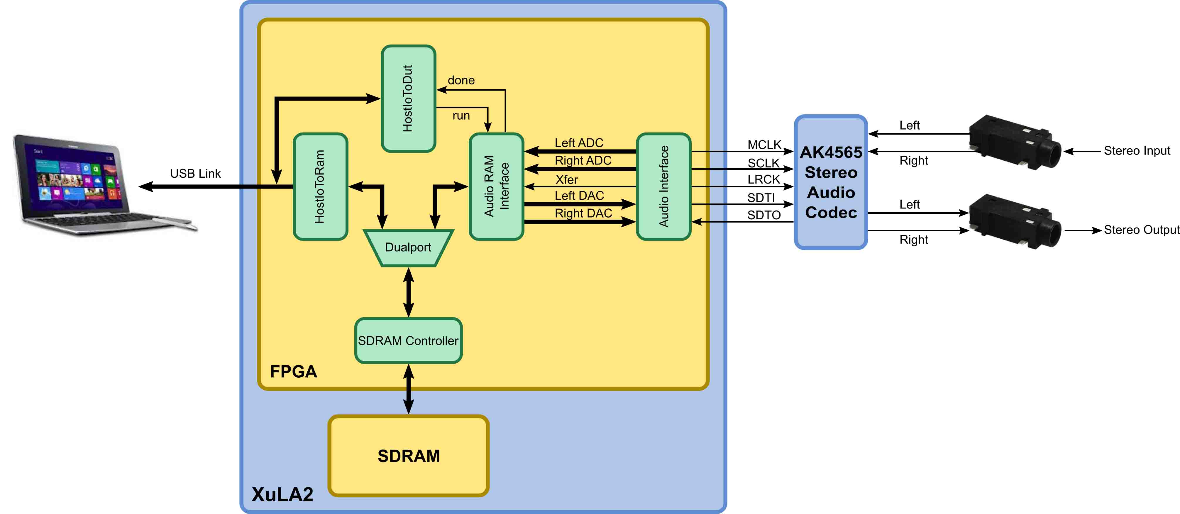
 The StickIt! AudioIO board has been out for a while, but the current FPGA design example that shows it off is pretty lame: a simple loopback that echoes the audio signal on the input back to the output. In my previous post, I developed a design to take samples from an eight-channel analog-to-digital converter (ADC), store them into SDRAM, and then upload them to a host PC. I decided to take that design as a starting point and modify it to use the AudioIO board for recording and playing back sound. The architecture of the modified FPGA design is shown below.
When active, the AK4565 codec chip on the AudioIO board samples the left and right input channels of a stereo audio signal. Simultaneously, it's also generating analog signals on the left and right output channels. The left/right input samples exit the chip serially as 20-bit values on the SDTO pin, while the output is driven by values received through the SDTI pin. The MCLK, SCLK, and LRCK pins are driven with the master clock, bit-shift clock, and left/right channel-select clock, respectively, and keep everything sync'ed up.

The Audio Interface module in the FPGA generates the codec clocks and also serializes/deserializes the output and input streams. When the Xfer signal pulses, the left and right audio samples sent serially from the codec are output as two 20-bit parallel words. At the same time, two 20-bit parallel words are latched so they can be serially transmitted to the codec to drive the left and right outputs.
The Audio Ram Interface module takes the two sample words and stores them in adjacent locations of the SDRAM as indicated by a pointer it maintains. Then, it fetches two output values from adjacent words of the SDRAM using another pointer. (Because the codec sample rate is only 48 KHz and the SDRAM runs at tens of MHz, the two writes and two reads of the SDRAM are completed long before the codec raises the Xfer signal again.) This process repeats until a specified number of transfers have occurred or the run signal is de-asserted.
The remainder of the original design is nearly unchanged: The HostIoToRam module lets the host PC upload the sampled stereo input and download new audio samples for output, while the HostIoToDut module is used to monitor and control the recording and playback processes.
For my first test, I wanted to output a known signal, sample it, and compare the two signals. (In essence, this is another loopback example, but I'd be able to quantitatively assess the results.) I hard-coded the following parameters into the top-level VHDL module:
Then I connected the stereo output of the AudioIO board back to its stereo input and wrote a Python script to do the following:
Here's a video of how this first test was assembled and run:
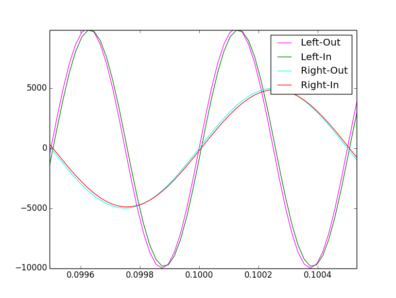
An initial test run showed the following results:

While similar, the sampled waves appear to be delayed versions of the generated sine waves. The delay is caused by the time it takes the codec chip to convert the digital output values into an analog signal and then re-convert that back into digital samples. It turns out this delay is about 34 sampling intervals. After modifying the Python script to shift the captured samples by this amount, you can see the sampled signals closely match the generated sine waves.

For my second application, I used the same architecture to build a simple record/playback device. I hooked a microphone to the input jack and a cheap speaker to the stereo output. Then I modified the top level of the FPGA design as follows:
Finally, I built a simple, two-button GUI that controls the sound recording and playback.
Here's a video of my simple record/playback system in action:
It works as expected, although the output from the cheap speaker doesn't have a lot of oomph to it.
So that's two additional, complete applications for the StickIt! AudioIO board. Hopefully, this will give people a more substantial starting point for their own projects.
Share on Twitter Share on Facebook Share on Reddit
Comments
New Comment