 Hearing talk about using schematics for FPGA design makes me feel like I'm standing at the top of a steep hill next to a toddler on a trike with loose wheel nuts. Some advice may be in order, to wit:
Get the hell off that bike! ARE YOU CRAZY!
Here's some ancient history: We used schematics back in the '80s for FPGA designs. We stuck with them through the '90s as FPGAs kept getting bigger, designs kept getting more complicated, and hardware description language (HDL) synthesizers got better and cheaper (and free!). Eventually, schematics got clubbed like a baby seal. Nobody uses 'em for anything serious, now.
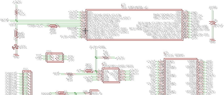
The problem with schematics is they're very low level: they show wires that carry voltages and current between components. That's great for analog design because that's mainly what analog designers are concerned with. But voltage and current are pretty far removed from the concerns of digital system designers (except for signal integrity guys, and they usually work with the PCB layout). To them, wires and buses convey semantics between various components. For instance, a bus isn't 32 wires having voltages between 3.3 volts and ground, instead it's a channel that carries the three-axis acceleration measurement from an IMU to a CPU. Wires and buses don't let you take advantage of abstraction. It's like using a programming language that only allows scalar variables and one-dimensional arrays. (Oh, yeah, that was called BASIC. Say hello to the '70s.) You can try tacking notes all over the schematic to explain what's going on, but eventually you end up looking like this guy.

But the main problem with schematics is those wires and buses have to get from one place to another on a two-dimensional page. You don't even have the advantage of a multi-layer PCB to route them. That means you'll spend an inordinate amount of time fiddling with a schematic trying to arrange the wires to show how the signals flow through the system. And all that effort is wasted: the FPGA routing software only cares about what's connected to what, not how beautifully you've made those connections. The only reason people make the effort is to try and put some higher-level meaning and context back into a representation that's too low-level to show it naturally. And if you do manage to create a meaningful schematic drawing, you'll be loath to re-architect and improve your design because you don't want to go through that again.
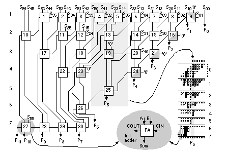
You can attempt to use hierarchical schematics to create submodules that hide the low-level wiring, and then connect those submodules with nice, clean buses. That doesn't solve the problem, but it does help. That is, as long as you get the system decomposed into the right submodules. And also that your schematic editor supports hierarchy. But then you still have to manually wire all the submodules together to build the higher-level modules. Here's a nice 6x6 Wallace-tree multiplier to make you think about that:

Maybe you believe there will be a pre-existing library of modules so you'll never have to do anything but connect them at a very high level. Well, there's no component faerie who magically delivers modules; somebody has to make them. And, eventually, you'll have to make some yourself because you'll create a design with some odd word-size or something. Or you'll need a state machine. (If you're thinking of using one of those graphical state machine editors for that, those things are even worse than schematic editors.)
Which brings us to a succinct assessment of the quality of schematic editors: they all suck donkeys! Schematic editors are the dumping ground of more bad user-interface concepts than iTunes. In any discussion of schematic editors, you'll always hear someone qualify their comments with "if you don't mind the quirky UI". Aside from that, many editors fail at implementing even the most basic functionality. It's easy to google stories of designs which had to be re-spun because wires that looked like they were connected on the schematic actually weren't.
Even if you were to find a schematic editor you liked, it's probably linked with a PCB layout editor and has to be coaxed to output netlists in the right format for your FPGA design flow. This problem can be avoided by using the schematic editor bundled into your FPGA vendor's software, but then you're trapped in a walled-garden: schematics aren't easily interchangeable between the different vendors' tools (intentionally). Sometimes the schematics don't even work with the next version of the same vendor's tools. Plus - amazingly - the schematic editors offered by the FPGA vendors are even more quirky than the stand-alone tools.
Next, consider the schematic files themselves. If you're working with a distributed team (or if you just want to make your design publicly available), you'll want to store them in an online repository like github or bitbucket. That brings up the issue of tracking changes in the schematic. Thankfully, a lot of schematic editors have abandoned binary file formats for text, but diffing these files doesn't give you an easily-understandable summary of what changed. Some people have tried to get around this with visual diffs of schematic images, and that works if you're doing simple additions/deletions of components or changing component values. But what happens if you move a section of your schematic a few pixels to make room for something? Boom! - your screen explodes with false positives as seen below. It's also an extra step to generate an image for every change, which means you'll eventually stop doing it.

All these problems go away if you describe your digital design using languages like VHDL or Verilog:
Now I know what you're saying: "VHDL and Verilog? Ugh! There's no way I want to mess with that stuff. How do you express the parallelism of hardware using a linear-text programming language?" Well, you're already capturing the hardware concurrency using schematics, which is not really any easier to do; you're just used to doing it that way. And, if you want, you can replicate your same "connect the parts together" approach using a structural HDL coding style (although that means you'll miss out on the increased productivity and efficiency provided by a behavioral/RTL HDL design style). And the pain of learning an HDL is only experienced once, but the agony of fiddling with wires on a schematic will be revisited for every design you build.
However, I do get what you're saying; I've cursed VHDL quite a bit over the years. But that's mainly from the strong, built-in type-checking that keeps me from shooting myself in the foot (it's like having an integrated lint checker that's always set for super-strict mode). So you might want to consider stepping up to one of the newer HDL languages like MyHDL, Migen, Chisel or PSHDL. Some of these languages are built on top of modern languages like Python and Scala which have an easier learning curve and come with advanced, full-featured development environments. On the back-end, these HDLs spit out Verilog and VHDL that can be fed into the FPGA synthesis tools. (You can think of these HDLs as fancy preprocessors.)
Of course, even after all I've said, you may still decide to use schematics. OK, that's fine; it's a free country (well, at least when choosing your design tools). But I hope I'm not ruining the surprise by telling you what waits at the end of your journey:

Comments
New Comment