 In my last blog post, I listed a bunch of online resources for the low-cost ESP8266 Wifi module. Now I'll go over how I got the module up and running in my own lab.
With any new piece of hardware, you want to make sure at least its basic functions are working before investing a bunch of time hooking up hardware and writing software for it. So I decided to connect the serial interface of the ESP8266 to my C232HM-DDHSL cable and exercise it with a few AT modem commands.
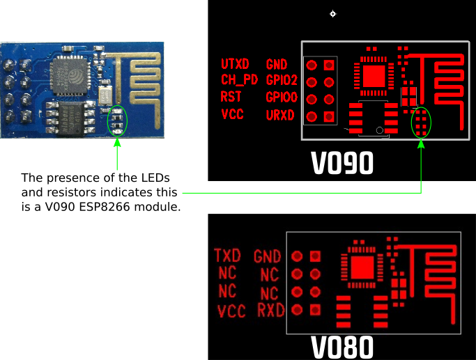
Before I could connect the cable, I had to know the pinout of the module. There are several types of ESP8266 modules floating around out there, so I had to determine which type mine was. I purchased it through Aliexpress from a company called Tumbler Hong (where the price has now dropped to $7.50 for two modules). There's not much help there since the catalog page doesn't list any specific model number for the module.
The Electrodragon ESP8266 page shows the component layout and pin assignments for the (older) V080 and (newer) V090 modules. The presence of the small LEDs on my module indicates it's a V090.

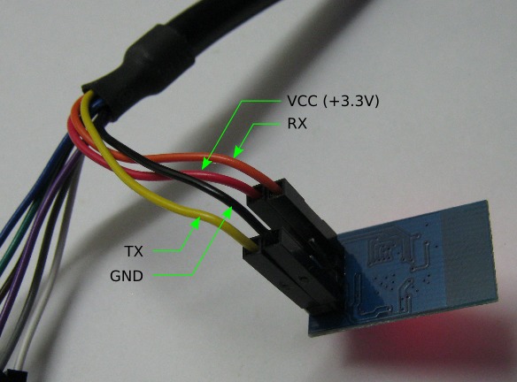
Knowing the version number, I can hook the leads of the C232HM cable to the module's pin header as follows:
| CH232HM Cable | ESP8266 Module Pin |
|---|---|
| Red (+3.3V) | VCC |
| Black (GND) | GND |
| Orange (TX) | URXD |
| Yellow (RX) | UTXD |

Since the C232HM cable operates with 3.3V, there's no need for any I/O level shifters between it and the 3.3V logic of the ESP8266 module.
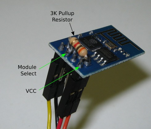
Also, as noted here, a pullup resistor from the module's chip-select pin to VCC is needed. The value of the resistor isn't too critical; I used 3K. Here's how I mounted it on my board:

Once the board is connected to the cable, it's just a matter of plugging the C232HM to a USB port on a PC. But then, how to talk to it? Since the C232HM just presents itself as a COM port on Windows, I decided to use the free Termite terminal emulator to send AT commands to the module. Here's a screencast of the results of sending some commands:
At this point, I've verified the ESP8266 module's serial interface and Wifi radio are both working. In my next post, I'll demonstrate interfacing the module to a ZPUino softcore processor running in a XuLA2 FPGA board.
Share on Twitter Share on Facebook Share on Reddit
Comments
why is it important to put the pull up resistor? can it be any resistor?
Link / ReplyThe chip-select has to be pulled high for the ESP8266 to function. The resistor value isn't critical. I've seen some examples where it is just tied directly to VCC.
Link / ReplyI have PICAXE starter kit, which includes a USB-Serial converter.
Link / ReplyI wonder if I could use this for communicating with am ESP8266?
I found a way to modify any FTDI USB-serial converter to comunicate with a PICAXE MCU. (http://letsmakerobots.com/node/19013)
What's your opinion, if I "deinvert" the 4 signals, could be used for the ESP8266?
Thx: Attila
I put together a list of all the different esp8266 types I could find here:
Link / Replyhttp://41j.com/blog/2015/01/esp8266-module-types/
Should help identify them. If you've seen any others in the wild I'd be interested in knowing about them.
New Comment