The StickIt! Board has been around since 2011, pretty much unchanged. Today that stops.
The new version of the StickIt! Board still allows you to connect the XuLA FPGA boards with various PMODs, but it also has a 20×2 connector for talking to the Raspberry Pi B+/2.
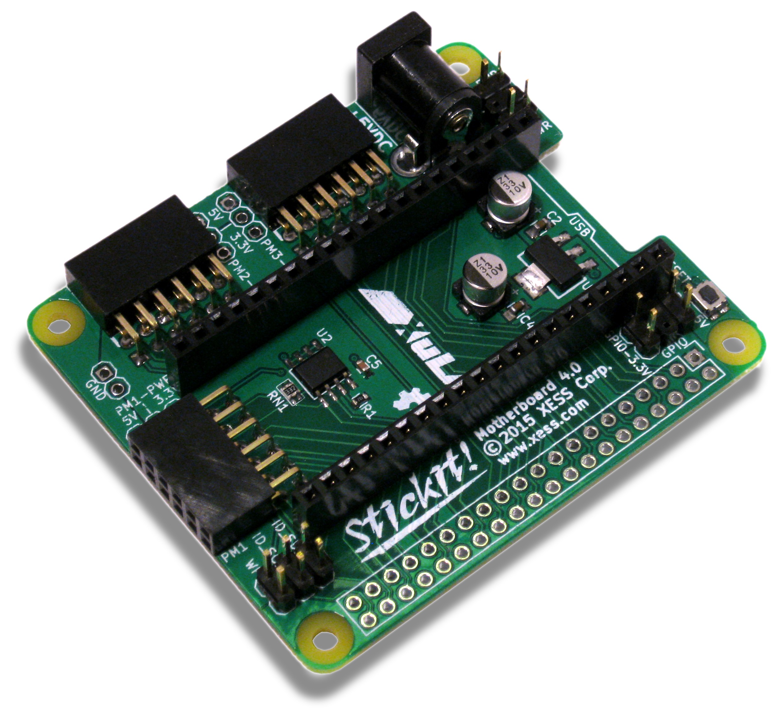
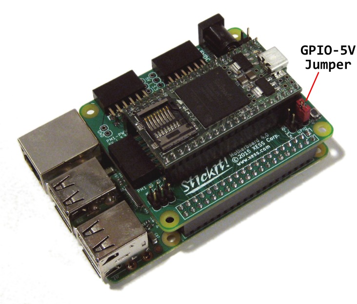
Here's what it looks like with a XuLA2 board inserted and attached to a Pi:
Now you can build applications where the Pi provides a standard linux environment coupled to the XuLA FPGA and some PMODs for doing specialized processing and interfaces.
Checkout the product page for all the details. Of course, it's all open source and you can get the documentation and design files on Github.
Share on Twitter Share on Facebook Share on Reddit
Comments
I was ready to order some until I looked at the schematics. It appears that many/most of the RPi I/O signals go to bot hPMON and XULA. This limits the functionality of both. I think it would have been much more useful for the PMOD's to be controlled by the XULA and a minimum number of RPi pins used to program and communicated with the FPGA. Let the remainder of the RPi I/O headers pass thru.
Link / ReplyHi, George.
Link / ReplyAs you would expect, I couldn't disagree more!
The XuLA2 has 33 I/O pins. The RPi has 26 GPIO pins. Each of the three PMOD has 8 I/O pins, for a total of 24. So it's obvious there's going to be some contention there.
PM1 is unusable when the RPi is attached because the RPi USB connector blocks it. The eight pins on this connector go to both the XuLA and the RPi, so the RPi is free to use these.
Seven of the PM2 pins connect only to the XuLA. Only one connects to both the XuLA and the RPi.
All eight pins of PM3 connect to both the XuLA and the RPi.
On the GPIO connector, 9 of the 26 pins connect only to the RPi.
So, if you use the PM2 and PM3 for connecting to PMODs, that will consume 8+8=16 pins to talk with the XuLA. That leaves 8+9=17 pins on the GPIO to talk between the RPi and the XuLA. If you could find a way to elevate the StickIt! board so PM1 is not blocked, then you could have all 24 bits going to PMODs and still have nine pins to communicate between the RPi and the XuLA.
I think the StickIt! Board provides a lot of flexibility to use the PMODs, XuLA and RPi pins as you see fit. If you connected a PMOD only to PM2, then you could use up to 25 pins to communicate between the RPi and XuLA. Or if you use all the PMOD sockets, you still have nine pins to talk between the RPi and the XuLA. I see no reason to have only a few of connections between the XuLA and RPi since that will definitely limit the bandwidth between them.
You say "Let the remainder of the RPi pins pass thru". To where? There's no reason to send them to the PMOD sockets. The RPi can already get to many of the PMOD pins directly or by programming the XuLA to provide a pathway through the FPGA.
Are you talking about stacking another board on top of the GPIO connector and communicating with that through the pass-thru pins? I think that's possible with the current board, although there may be some issues with signal contention. But providing the most bandwidth possible between the RPi and the XuLA is probably going to be of benefit to more customers than stacking multiple HATs.
Of course, you have another option since the StickIt! Board is OSHW: you can grab the schematic and PCB files and strip out the connections you don't think are needed and have your own version built. You could get ten PCBs for around $25, stuff a few components on them and then have what you want.
New Comment