 My Twitter friend, Jeremiah Johnson, sent me a couple of LED panels
in January.
These things retail for about $40 each, so I thought I should at least develop a driver for him.
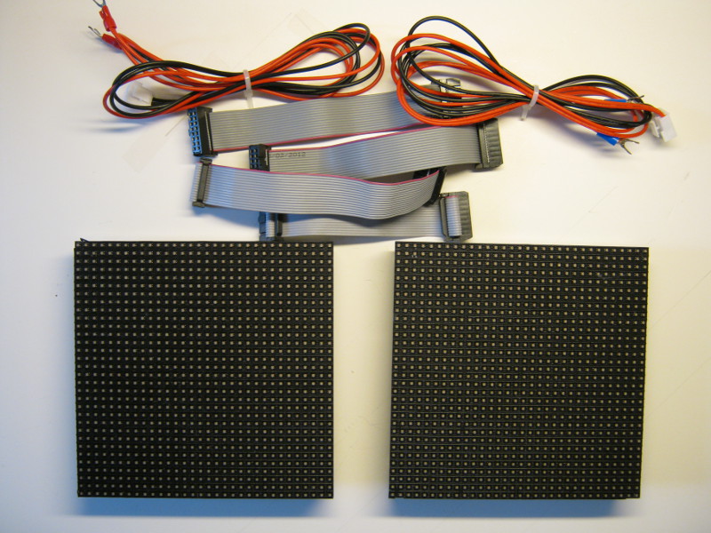
From the picture, you can see the panels are 32 × 32 arrays of RGB LEDs. Ribbon cables are used to concatenate panels to form larger displays. There's a total of 2 × 32 × 32 × 3 = 6,144 red, green and blue LEDs on both boards which can supposedly take up to 4 amps of current, but I got away with using a single 1A power adapter.

The panels don't contain a frame buffer to store an image: the LEDs have to be continuously refreshed. This is done by shifting-in a sequence of bits to activate selected RGB LEDs in a given row and then latching those bits to drive the LEDs while another set of bits is shifted in for the next row. An entire image is created by moving rapidly from one row to the next. And if you adjust the proportion of how often a particular LED bit is on or off, you can also display colors of varying intensity.
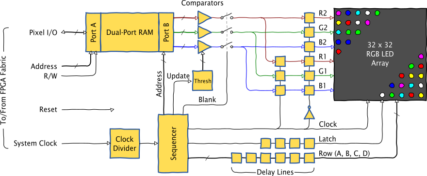
Naturally this takes a fair amount of bit-twiddling over a short period of time, but that's a perfect job for an FPGA. The block diagram for the FPGA-based LED panel driver that I built is shown below.

The image is stored in a dual-port RAM that is written (or read) by some other logic circuit in the FPGA (usually something like a processor). The LED panel driver reads the image pixels from the other port of the RAM. There is no need to double-buffer the RAM: the high-bandwidth interface to the rest of the FPGA means that any re-write of the image occurs much too quickly to be noticed. (Of course, you can make a buffer in some other part of the FPGA where you slowly build an image and then quickly dump it into the dual-port RAM, but that can be done as needed on a case-by-case basis so as not to reduce the overall area-efficiency of the display circuitry.)
Each word of RAM is divided into three bit-fields which each hold the intensity value for the red, green and blue LEDs of a pixel. The bit field values are compared to a threshold and the associated LED is turned on if the bit field value is greater than the threshold. The intensity of the pixel colors is varied by scanning a line of pixels multiple times while ramping-up the threshold. For example, a red LED will be on twice as much (and shine twice as brightly) if its bit field has the value 42 as compared to when it stores 21.
The LED panel is divided into top and bottom halves, so the RAM stores pixels for one half in the locations with even addresses and pixels for the other half at odd addresses. The sequencer outputs odd and even addresses on alternate clock phases. The RGB bits for the pixel in one half of the panel are stored temporarily while the bits for the pixel in the other half are generated. Then both sets of bits are sent simultaneously to the panel on the falling-edge of the clock so they'll be stabilized before the rising edge of the clock shifts them into the panel.
The sequencer also generates the latching signal and selects the active row of the display. Because several clock cycles are needed to fetch pixels from the RAM and do the threshold comparisons, the latch and active-row signals have to be delayed a few cycles to get them back in sync with the RGB signals.
The sequencer also solves a timing problem that arises when it comes time to change the active row of the panel. If the row is changed before the latch is activated, then the pixels for the previous row will appear faintly in the new row before the new pixel values are established. Likewise, if the row changes after the latch signal, then the new pixels will appear briefly in the previous row before they show up in the desired location. Finally, if a pixel is on but then has its driver turned off, the charge residing in the wiring capacitance can partially illuminate other pixels in the same column. These are examples of ghosting. Since a row of pixels is scanned multiple times while ramping the threshold to create varying colors, ghosting can be eliminated by doing one final scan where all the pixels are off (or "blanked") before the row address is changed. While this leads to a slight diminution in the overall pixel brightness, it's much less noticeable than the partially-on pixels that occur with ghosting.
You can examine the VHDL code for the LED panel driver here. Some things to note are:
The circuitry can resize itself at compile time by setting a few generic parameters that describe the width and height of the LED panel and how many are strung together.
The dual-port RAM is done using VHDL inference instead of instantiating a vendor-specific block RAM. That makes it easier to port this module to other FPGA families.
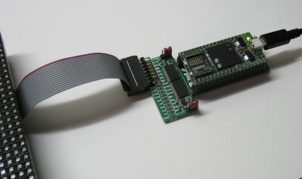
The VHDL file also contains a version of the LED panel driver with a Wishbone interface. This makes it easy to attach as a peripheral to the ZPUino softcore processor. The combined ZPUino plus LED panel driver can be loaded into a XuLA2 board that is then inserted into a Logic Pod. The Logic Pod provides a convenient connector for mating with the cable to the LED panel; the voltage translation capabilities of the Logic Pod are not needed since the LED panels accept 3.3V logic levels.

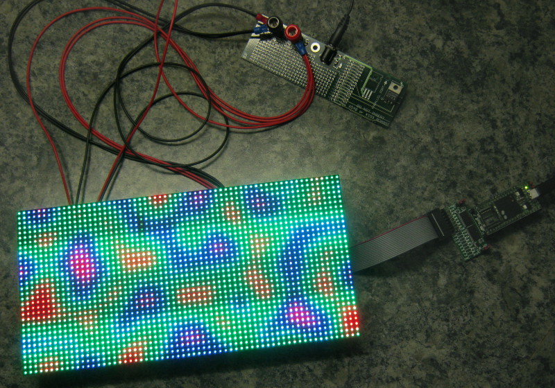
With the ZPUino + LED panel driver, it becomes possible to generate graphics just by writing Arduino sketches. Because the panel driver offloads all the real-time processing needed to refresh the display, the ZPUino processor just has to concern itself with loading an image into the RAM. I took some code from here and adapted it to generate Perlin noise on a 64 × 32 display:

That's about it, but in closing I'll tell you a few things I tried that didn't work so you won't repeat them:
I built the driver starting from the pinout and my best guess as to how the circuitry expected the signals to toggle. Big mistake. I ended up rediscovering all the ghosting problems that others had already found and solved. Next time: read the blogs!
I originally used a random number generator (RNG) for the threshold. I figured that creating a uniform distribution between 0 and 255 would give the same effect as a linear ramp and would require less sequencing and circuitry. Unfortunately, I noticed a lot of sparkling and correlation effects in the pixels even when using an eight-bit slice of a 32-bit RNG.
The output-enable control input for the LED panels is practically useless. I tried to use it to eliminate ghosting by disabling the outputs when the row was switched, but it had no effect. I ended up just enabling the panel all the time by pulling this input to ground.
Share on Twitter Share on Facebook Share on Reddit
Comments
Please, what application do you use to make the nice drawings.
Link / ReplyHi, William. I use the FOSS vector-drawing program Inkscape.
Link / ReplyNew Comment