When the XuLA2 was released, I still didn't have an easy-to-use controller module to interface the FPGA with the SD Flash card. But now I do and you can get it here.
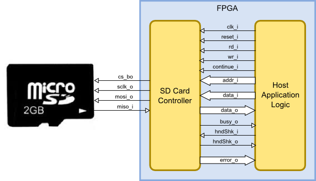
Here's a block diagram that shows the various control signals and datapaths for the SD card controller module.

After looking at the diagram, maybe you're thinking that "easy-to-use" isn't the best adjective to apply to this module. But it's really pretty simple:
First of all, you have to give the controller a clock signal on the clk_i input with a higher frequency than the serial clock sent to the SD card through the sclk_o output. You can set generic parameters for the controller to tell it the master clock frequency (100 MHz), the SCLK frequency for initialization (400 KHz), the SCLK frequency for normal operation (25 MHz), the size of data sectors in the Flash memory (512 bytes), and the type of card (either SD or SDHC). I typically use a 100 MHz clock if I'm running an SD card with a 25 Mbps serial data stream.
Pulsing the reset_i input high and then bringing it low again will make the controller initialize the SD card so it will work in SPI mode. Basically, it sends the card the commands CMD0, CMD8, and then ACMD41 (which is CMD55 followed by CMD41). The busy_o output will be high during the initialization and will go low once it is done.
After the initialization command sequence, the SD card will send back an R1 response byte. If only the IDLE bit of the R1 response is set, then the controller will repeatedly re-try the ACMD41 command while busy_o remains high.
If any other bit of the R1 response is set, then an error occurred. The controller will stall, lower busy_o, and output the R1 response code on the error_o bus. You'll have to pulse reset_i to unfreeze the controller.
If the R1 response is all zeroes (i.e., no errors occurred during the initialization), then the controller will lower busy_o and wait for a read or write operation from the host. The controller will only accept new operations when busy_o is low.
To write a data block to the SD card, the address of a block is placed on the addr_i input bus and the wr_i input is raised. The address and write strobe can be removed once busy_o goes high to indicate the write operation is underway. The data to be written to the SD card is passed as follows:
hndShk_o output.data_i input bus and raises the hndShk_i input.hndShk_o output.hndShk_i input.This sequence of steps is repeated until all BLOCK_SIZE_G bytes of the data block are passed from the host to the controller. Once all the data is passed, the sector on the SD card will be written and the busy_o output will be lowered.
To read a block of data from the SD card, the address of a block is placed on the addr_i input bus and the rd_i input is raised. The address and read strobe can be removed once busy_o goes high to indicate the read operation is underway. The data read from the SD card is passed to the host as follows:
hndShk_o output when the next data byte is available.data_o output bus and raises the hndShk_i input.hndShk_o output.hndShk_i input.This sequence of steps is repeated until all BLOCK_SIZE_G bytes of the data block are passed from the controller to the host. Once all the data is read, the busy_o output will be lowered.
If an error is detected during either a read or write operation, then the controller will stall, lower busy_o, and output an error code on the error_o bus. You'll have to pulse reset_i to unfreeze the controller. That may seem a bit excessive, but it does guarantee that you can't ignore any errors that occur.
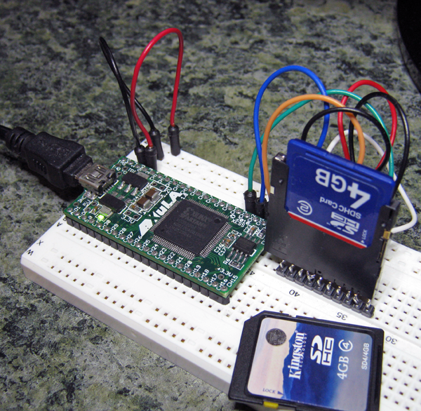
The SD card controller was successfully tested with a 2GB Sandisk SD card, a 4GB Sandisk SDHC card, and a 4GB Kingston SDHC card. The controller module was also ported to the original XuLA and tested using the setup shown below.

Comments
Hello Dave,
Link / Replyi have a question regarding the Xula2-LX9 board and the SD Card. I'm a beginner with VHDL and FPGAs and i want to test the SD Card on this board. I'm not sure how to do that. I downloaded the following files from this homepage:
- SDCard.vhd
- ClkGen.vhd
- Common.vhd
- SyncToClk.vhd
- HostIo.vhd
If i import these files with Xilinx ISE, i am able to synthesize. So far, so good. How can i test the functionality now? Do i need a special Programm on Windows 7 to set the Read/Write commands?
Another point is, when i open the RTL Schematic, i recognize that many I/O's from HostToDut are not connected. I will upload some Screenshots in the next time.
I would be glad if you could help me.
Thank you
best regards
Alex
Hi, Alex.
Link / ReplyYes, you need a Python script that loads files from the PC to the microSD card and can read them back. Unfortunately, I lost this script and I'll have to recreate it! **Give me a few days to do that.**
Yes, the HostIoToDut does have a lot of unused I/O's. I put those in so that it could be easily expanded. Any unused I/O is removed during synthesis so it shouldn't affect anything.
Hi, Alex. I added a Python script (https://github.com/xesscorp/XuLA2/blob/master/FPGA/SdcardCtrlTest/SdcardTest.py) to transfer a block of data to/from the SD card.
Link / ReplyIt's a slow interface that's only intended to test the SD card controller. For a faster transfer, I'd create a memio interface in the FPGA so the PC could just do block reads and writes without messing with the individual read, write, handshake and busy signals.
Hi Dave,
Link / Replythank you very much for your help. It works really good with your Python script. I wanted to read out the SD Card Information from Windows directly but this does not work. Windows wants to format the SD Card because he can't see any file system. Do i destroy the current file system if i write the sd Card via the Xula board?
Is it complicate to read out data from a file system?
best regards
Alex
Hi, Alex.
Link / ReplyThe Python utility just reads or writes a 512-byte block of the SD card. This is the lowest level of file I/O. Windows FAT or NTFS file systems add more layers above this to implement arbitrary-sized files built from non-contiguous blocks. At the very least, this involves storing file names, sizes and link pointers in addition to the data blocks. When you just over-write a block of the SD card with raw data, you destroy a lot of this metadata and Windows can't understand the file organization on the card any more.
You could build a finite-state machine or small processor in the FPGA that creates a file system when it writes data to the card. I've never investigated how hard this might be, but I would assume it's non-trivial for the general case. Maybe there is an easy way to do it by introducing enough simplifications or restrictions on the data you want to store.
New Comment