People at the 2012 NC Maker Faire were asking me if the documentation for my projects was online. (OK, one person asked, but that's enough to get me going.) So here's a description of my first project, the Reflex Circle, and how I built it.
My girlfriend's daughter likes to play a simple game at the arcade which consists of a ring of lights and a button. The lights come on sequentially and she has to hit a button at the right time to stop the light at the top of the circle. So I built a version of that. Here's a video of of me playing it:
The construction of this project is pretty straightforward but time consuming. I started with a wooden console that my girlfriend's father built for me.
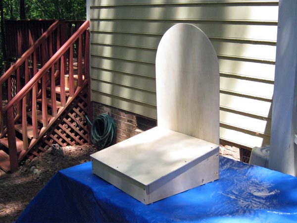
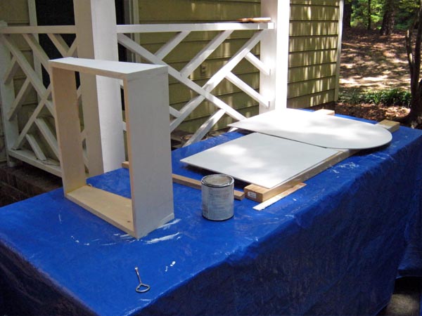
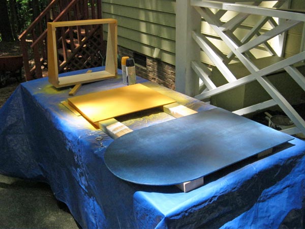
Then there's the boring work of priming and painting it. I chose navy blue and gold to match my company's colors.
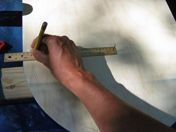
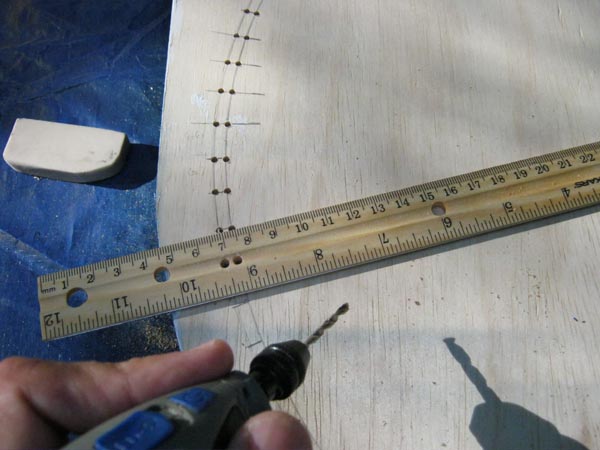
Next I had to mount the LEDs in a ring on the console display. (Probably should have done this before painting it - oh, well, live and learn.) I took a cheap wooden ruler and drilled a hole at one end to mount it on a pivot nail at the center of the circle. Then I drilled two more holes in the ruler about 9" away. These were spaced to accomodate the legs of the LEDs I was going to used. Then I used the ruler like a compass to draw two concentric circles on the back of the display board.
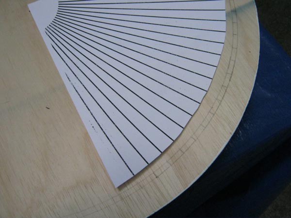
There were going to be 90 LEDs in the circle, so they would be spaced at 4° intervals. There was no way I was going to measure those individually! If I made an error of 0.1° each time, then I could be off by 9° by the time I completed the circle. Instead, I laid out a 90° pie slice of 4° segments in Inkscape and printed that onto some card stock. I used that as a template to mark off the spots on each quadrant of the circle.
Once I had the appropriately-spaced marks, I used the ruler again as a guide while I drilled the holes.
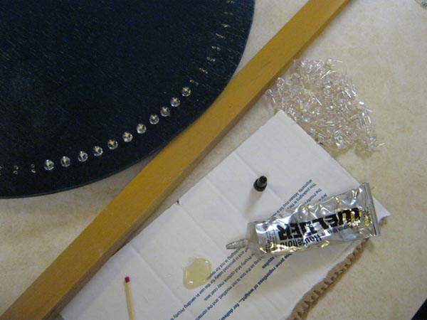
Then I mounted the LEDs into the board using a drop of glue on the base of each one. (I used 8mm, strawhat LEDs that mimic the non-directional glow of incandescent lights better than normal LEDs.)
Now it's all wires, wires, wires! I'm using charlieplexing so I can drive all 90 LEDs using only ten wires. I divided the ring into nine segments of ten LEDs each and marked the direction of travel for the activation of the LEDs. The LEDs were placed so all their anodes were in the outer ring which made it easy to connect all the anodes of each section together.
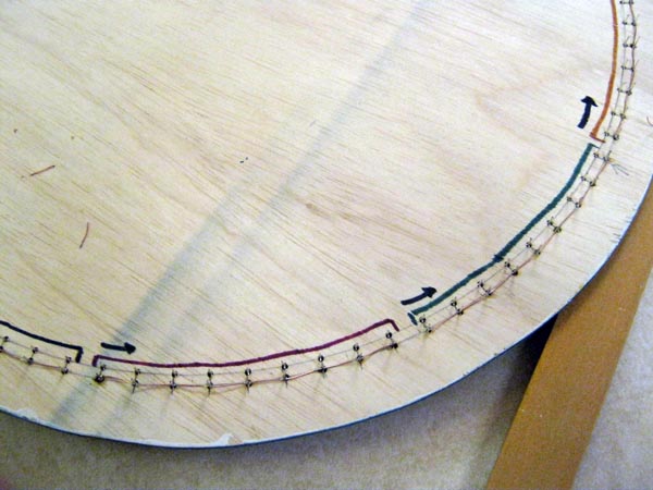
The cathode wiring is a bit more complicated but it still follows a regular pattern. I labeled all the LEDs and just "connected the dots".
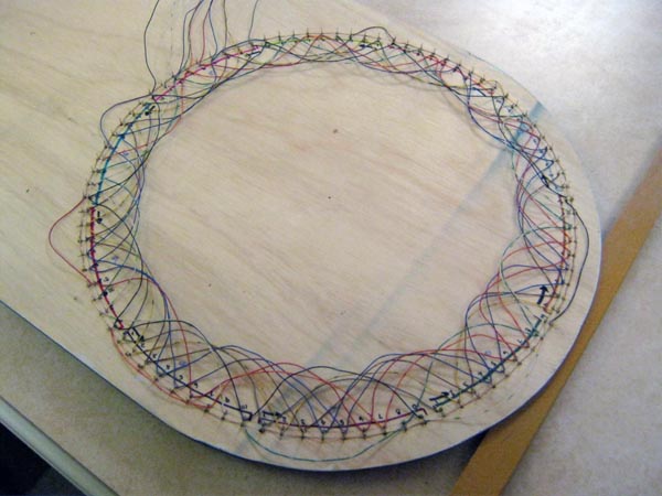
Once all the wiring was in place, I manually drove the wires to check that the LEDs lit up in the correct order. (I had already tested the individual LEDs before assembly to make sure there were no duds.)
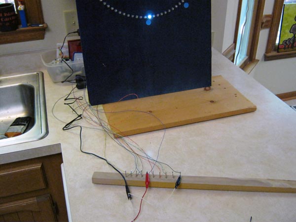
For sound effects, I dismantled a pair of computer speakers and mounted the speakers and amplifier PCB on the back of the display board. I also used a piece from the speaker case on the front of the display board to cover the speaker holes I drilled into it.
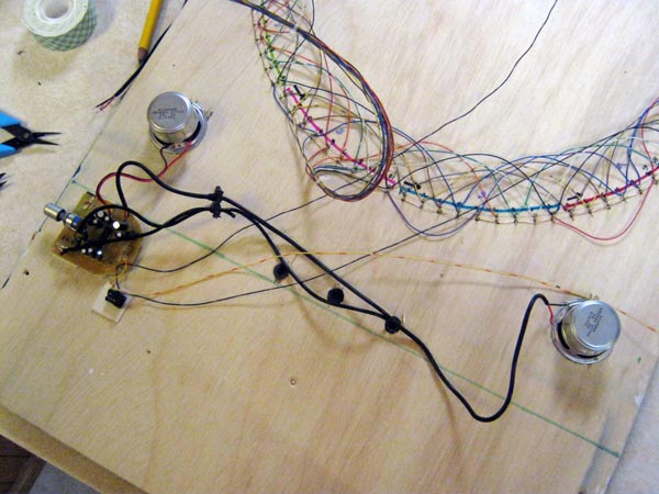
Then I drilled some holes and inserted grommets so I could bring all the wires from the display board to the control circuitry. Since this was for a Maker Faire, I mounted a XuLA-200 FPGA board and StickIt! motherboard on top of the console so people could see it. I connected a 20-bit audio codec board to those so the FPGA could drive the speakers.
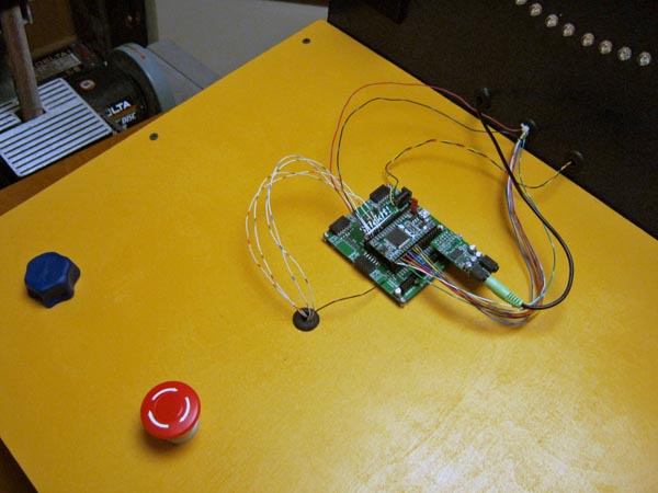
I removed the locking mechanism from a cheap emergency switch so I could use it as a momentary pushbutton to start and stop the LED circulation. A rotary encoder is used to control the game's level of difficulty. (I built a knob for the encoder shaft using a piece of Sculpey clay.) Here's the wiring that goes on underneath the control board.
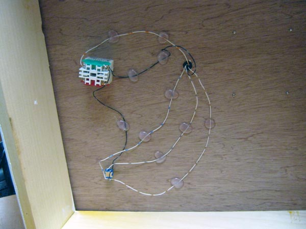
Connecting all the wires to the FPGA was a little more difficult than I had thought it would be. I had purchased a 10' length of 24-pair CAT3 cable that I pulled apart to get 48 individual wires with unique color patterns. That let me color-code all my wiring so I could keep things straight. Unfortunately, these were 24-gauge wires and they were too thin to plug securely into the sockets of the StickIt! board. So I had to solder the wires to 0.025" header pins and insert those into the sockets.
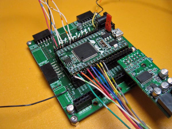
With all the hardware assembled, all that was left was programming the game-play into the FPGA. Because I spent so much time working on another Maker Faire project (the Voice Warper, which I'll describe in another blog post), I didn't get around to this until 12 hours before the start of the Faire. Here are the various components I placed into the FPGA (you can see the FPGA project source code here):
I also wanted to build a sound generator to make various sounds depending upon whether the player won or lost, but I ran out of time. I did get a freebie, however: switching noise was picked up by the audio circuit and that made a sound as the LED was circulating around the ring. I accepted that unexpected gift at 6AM on the day of the Maker Faire and I declared the project done. I baked the clay for the last bit of artwork, mounted it on the display board and headed to the Faire.
The game got a lot of use from both kids and adults at the Maker Faire. Everyone seemed to enjoy playing it even though it seems very simple. They would compete to see who could win using the smallest LED activation arc. I noticed that teenagers were able to play using only a single LED in the arc, but older players needed a larger arc in order to win. I baked a batch of fifty cookies while working on the FPGA programming which I passed out to various people during the day based on their game play. (Well, actually I was just giving them out for no particular reason at all.) All-in-all, it turned out to be a big success.
Next year I'm planning to add voice output to this game so it can shout out insults based on the player's results (for example, "Are you even looking at what you're doing?!?"). Perhaps then I'll rename the game to the Circle Jerk.
Comments
New Comment