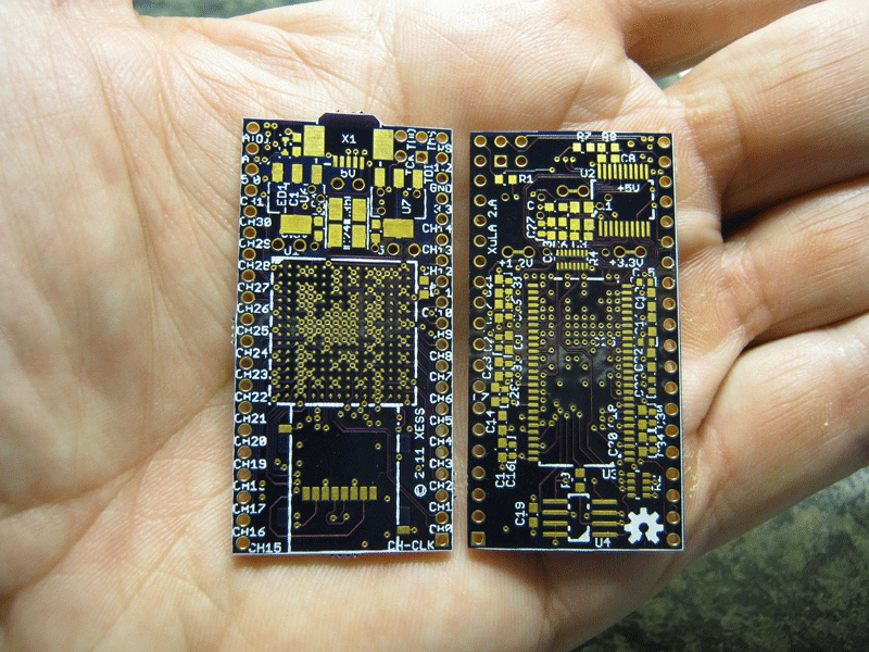
I got the prototype PCBs for the next version of the XuLA Board from @laen's service a few weeks ago. Here's the front and back of the bare board:

My goal with this version was to make the simplest changes that would bring the biggest perceived benefits to the customer. That's usually accomplished by just making everything bigger, so I did the following:
| Resource | XC3S200AVQ100 | XC6SLX25FTG256 |
|---|---|---|
| #LUTs | 4K | 24K |
| #BRAMs | 16 | 52 |
| #Multipliers | 16 | 38 |
| #DCMs | 4 | 4 |
| #I/Os | 68 | 186 |
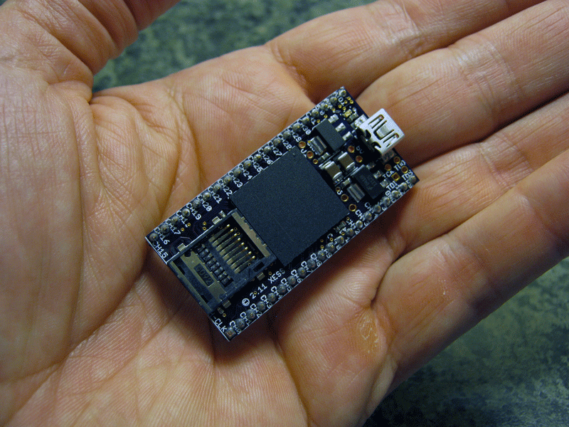
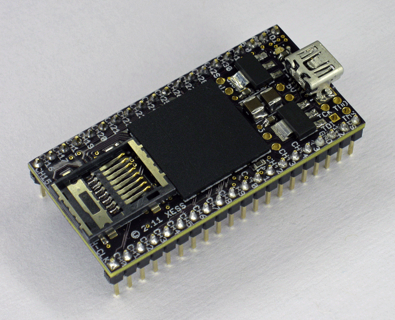
Making room for the MicroSD socket required me to push some of the other XuLA components around. After assembling the parts onto a prototype, the board ended-up looking like this:


It's a bit cramped and it looks like the components have been forced in there, but that's the only way I could find to make it all fit in the same form factor as the original XuLA. Unfortunately, beauty takes a backseat here.
In order to get an FPGA with a lot more logic resources than the Spartan-3A, I had to use a Spartan-6 in a package with a lot more I/O. But even after connecting all the SDRAM and MicroSD signals to the FPGA, there were still more than 100 pins left-over on the BGA package. I couldn't add any more I/O to the board prototyping header and remain compatible with the original XuLA, so I just had to waste 'em. That's a first for me; I'm usually struggling to find enough FPGA pins to connect everything.
Given the things I did, I started referring to the new XuLA board as a "Big, Ugly Pig". Seems to fit.
After assembly, the first thing I like to do when I'm bringing-up a new FPGA board (after checking for power/ground shorts) is just download a simple bitstream that makes an LED blink. But the XuLA doesn't have any on-board LEDs that the FPGA can drive. Luckily, I already had some external seven-segment LED hardware built for the original XuLA, so I could just use that with the new board. Here's a video of me downloading a bitstream that makes the new XuLA output a string of digits:
Passing this first test shows a few things:
That's pretty good for a first trial. Now I can start testing the other components connected to the FPGA.
Comments
New Comment